Wireless Networks

Introduction to Wireless Networks

Principles and Fundamentals
First Generation Cellular Systems

Second Generation Cellular Systems

Third Generation Cellular Systems

Fixed Wireless Access Systems

Wireless ATM and Ad Hoc Routing

Personal Area Networks (PANs)

Economics of Wireless Networks


Untitled Document
Introduction to Wireless Networks

Wireless Networks

by P. Nicopolitidis, M.S. Obaidat, G.I. Papadimitriou, A.S. Pomportsis, John Wiley,2003.

1.1 Evolution of Wireless Network
1.1.1 Early Mobile Telephony
1.1.2 Analog Cellular Telephony
1.1.3 Digital Cellular Telephony
1.1.3.1 GSM
1.1.3.2 HSCSD and GPRS
1.1.3.3 IS-95
1.1.4 Cordless Phones
1.1.5 Wireless Data System
1.1.5.1 Wide Area Data Systems
1.1.5.2 Wireless Local Area Networks(WLANS)
1.1.5.3 Wireless ATM(WATM)
1.1.5.4 Personal Area Networks(PANs)
1.1.6 Fixed Wireless Links
1.1.7 Satellite Communication Systems
1.1.8 Third Generation Cellular Systems and Beyond
1.2 Challenges
 
Wireless transmission has found widespread use in communication system only in the last 15-20 years.
 
The popularity of wireless communication systems is due to advantages compared to wireline systems.
 
The most important if these advantages mobility and cost savings.
 
Wireless networks are also useful in reducing networking costs in several cases.
 
The fact can be extremely useful:
   
Network deployment in difficult to wire areas,such is the case for cable placement in rivers, oceans, etc.
   
Prohibition of cable deployment. This is the situation in network deployment in several cases, such as historical buildings.
   
Deployment of a temporary network. In this case, cable deployment does not make sense.
 
Deployment of a wireless solution, such as a WLAN is an extremely cost-efficient solution for the scenarios described above.

BackToTop
1.1 Evolution of Wireless Network
 
 
It is more logical to assume that the origin of wireless networks , as we understand them today , starts with the first radio transmission.
 
The origins of radio-based telephony date back to 1915, when the first radio-based conversation was established between ships

BackToTop
1.1.1 Early Mobile Telephony
 
 
In 1946, the first public mobile telephone system, known as Mobile Telephone System(MTS), was introduced in 25 cities in the US.
 
MTS was an analog system, meaning that it processed voice information as a continuous waveform.
 
The system was half-duplex, meaning that at a specific time the user could either speak or listen.
 
MTS utilized a Base Station(BS) with a single high-power transmitter that covered the entire operating area of the system
 
However, since these BSs utilized he same frequencies, they needed to be sufficiently apart form one another so as not to cause interference to each other
 
Major limitations of MTS were the manual switching of calls and the fact that a very limited number of channels was available

BackToTop
1.1.2 Analog Cellular Telephony
 
 
MTS used the spectrum inefficiently, thus providing a small capacity.
 
The fact that the large power of BS transmitters caused interference to adjacent systems plus the problem of limited capacity quickly made the system impractical.
 
A solution to this problem was found through the use of the cellular concept, which would bring about a revolution in the area of mobile telephony a few decades later.
 
Originally proposed in 1947, the cellular concept replaces high-coverage BSs with a number of low-coverage stations.
 
The area of coverage of each such BS is called a ‘cell’.
 
The available spectrum is partition into channels and each cell uses its own set of channels.
 
This concept is known as frequency reuse and allows a certain channel to be used in more than one cell, thus increasing the efficiency of spectrum use.
 
Each BS is connected via wires to a device known as the Mobile Switching Center(MSC).
 
The first generation of cellular systems (1G system) was designed in the late 1960s can be thought as descendants of MTS since they were of also analog systems.
 
The first commercial analog system in the Us, known as Advanced Mobile Phone System(AMPS),offer only voice transmission.

BackToTop
1.1.3 Digital Cellular Telephony
 
 
Analog cellular systems were the first step for the mobile telephony industry.
 
Despite their significant success, they had a number of disadvantages were alleviated by the second generation of cellular systems(2G system), which represent data digitally.
 
This is done by passing voice signals through an Analog to Digital (A/D) converter and using the resulting bitstream to modulate an RF carrier.
 
Compared to analog system, digital systems have a number of advantages :
   
Digitized traffic can easily be encrypted in order to provide privacy and security
   
Analog data representation made 1G systems susceptible to interference, a highly variable quality of voice calls. In digital systems, it is possible to apply error detection and correction techniques to the voice bitstream.
   
In analog system, each RF carrier is dedicated to a user, regardless of whether the user is active or not. In digital systems, each RF carrier is shared by more than one user.

BackToTop
1.1.3.1 GSM
 
 
Throughout Europe, a new part of the spectrum in the area around 900MHz has been made available for 2G systems.
 
Its name was ‘Global System for Mobile Communication’.
 
Nowadays, it is the most popular 2G technology, this popularity is not only due to its performance, but also due to the fact that it is the only 2G standard in Europe.

BackToTop
1.1.3.2 HSCSD and GPRS
 
 
Another advantage of GSM is its support for several extension technologies that achieve higher rates for data applications.
 
Two such technologies are High Speed Circuit Switched Data(HSCSD) and General Packet Radio Service(GPRS).
 
Contrary to GSM, it gives more than one time slot per frame to a user, hence the increased data rates.
 
GPRS operation is based on the same principle as that of HSCSD : allocation of more slots within a frame. However, the difference is that GPRS is packet-switched, whereas GSM and HSCSD are circuit-switched.

BackToTop
1.1.3.3 IS-95
 
 
In 1993, IS-95, another 2G system also known as cdma one, was standardized.
 
Is-95 utilizes Code Division Multiple Access (CDMA).
 
In IS-95, multiple mobiles in a cell whose signals are distinguished by spreading them with different codes, simultaneously use a frequency channel.Thus, neighboring cells can use the same frequencies.

BackToTop
1.1.4 Cordless Phones
 
 
Cordless telephones first appeared in the 1970s and since then have experienced a significant growth.
 
They were originally designed to provide mobility within small coverage areas, such as homes.
 
Cordless telephones comprise a portable handset, which communicates with a BS connected to the Public Switched Telephone Network(PSTN).
 
The evolution of digital cordless phones led to the DECT system. This is a European cordless phone standard that provides support for mobility.
 
A standard similar to DECT is being used in Japan. This is known as the Personal Handy-phone System(PHS). It also supports handoff between BSs.

BackToTop
1.1.5 Wireless Data System
 
 
Wireless data systems are used for transmission of data.
 
These systems are characterized by bursty transmissions : unless there is a packet to transmit, terminals remain idle.

BackToTop
1.1.5.1 Wide Area Data Systems
 
 
These systems offer low speeds for support of services such as messaging, e-mail and paging.
 
Paging systems. These are one-way cell-based systems that offer very low-rate data transmission towards the mobile user.
 
Paging systems work by broadcasting the page message from many BSs both terrestrial and satellite. Terrestrial systems typically cover small areas whereas satellites provide nationwide coverage.
   
Mobitex.
   
This is a packet-switched system developed by Ericsson for telemetry applications.
   
Ardis.
   
This circuit-switched system was developed by Motorola and IBM.
   
Multicellular Data Network(MCDN).
   
MCDN was designed for Internet access and thus offers significantly higher speeds than above systems

BackToTop
1.1.5.2 Wireless Local Area Networks(WLANS)
 
 
WLANs are used to provide high-speed data within a relatively small region, such as a small building.
 
The first attempt to define a standard was made in the late 1980s by IEEE Working Group 802.4.
 
As a result, the Executive Committee of IEEE Project 802 decided to establish Working Group IEEE 802.11.
 
The first 802.11 standard offered data rates up to 2 Mbps using either spread spectrum transmission in the ISM bands or infrared transmission.
 
In 1999, two supplements to the original standard were approved by the IEEE Standards Board.
 
The first standard, 802.11b, extends the performance of existing 2.4GHz physical layer, with potential data rates up to 11Mbps.
 
The second standard, 802.11a aims to provide a new , higher data rate (from 20 to 54 Mbps) physical layer in the 5 GHz ISM band.
 
IEEE 802.11 is often referred to as wireless Ethernet and can operate either in an ad hoc or in a centralized mode.
 
An ad hoc WLAN is a peer-to-peer network that is set up in order to serve a temporary need.

BackToTop
1.1.5.3 Wireless ATM(WATM)
 
 
WATM aims to combine the advantages of freedom of movement of wireless networks with the statistical multiplexing and QoS guarantees supported by traditional ATM networks.

BackToTop
1.1.5.4 Personal Area Networks(PANs)
 
 
PANs are the next step down from LANs and target applications that demand very short-range communications.
 
The first attempt to define a standard for PANs dates back to an Ericsson project in 1994, which aimed to find a solution for wireless communication between mobile phone and related accessories.
 
This project was named Bluetooth.

BackToTop
1.1.6 Fixed Wireless Links
 
 
Contrary to the wireless systems presented so far, fixed wireless system lack the capability of mobility.
 
Such systems are typically used to provide high speeds in the local loop, also known as the last mile.
 
Fixed wireless systems are either point-to-point or point-to-multipoint systems.
 
Point-to-multipoint is the most popular form of providing fixed wireless connectivity, since many users can connect to the same antenna transceiver. :
 
The most common fixed wireless system are presented below and are typically used for high-speed Internet access :
 
ISM-band systems.
 
MMDS. (Multipoint Multichannel Distribution System)
 
LMDS. (Local Multipoint Distribution System)

BackToTop
1.1.7 Satellite Communication Systems
 
 
The first real communication satellite was the AT&T Telsart1, which was launched by NASA in 1962.
 
From the Telstar era to today, satellite communications have enjoyed an enormous growth offering services such as data, paging, voice, TV broadcasting, Internet access and a number of mobile services.

BackToTop
1.1.8 Third Generation Cellular Systems and Beyond
 
 
Despite their great success and market acceptance, 2G systems are limited in terms of maximum data rate.
 
In order to provide for efficient support of such services, work on the Third Generation(3G) of cellular systems was initiated by the International Telecommunication Union (ITU) in 1992.
 
The outcome of the standardization effort, called International Mobile Telecommunication 2000(IMT-2000), comprises a number of different 3G standard.
 
These standards are as follows :
 
EDGE, a TDMA-based system
 
Cdma2000, a fully backwards-compatible descendant of IS-95
 
WCDMA, a CDMA-based system
 
As far as the future of wireless networks is concerned, it is envisioned that evolution will be toward an integrated system, which will produce a common packet-switched platform for wireless systems, this is the aim of the Fourth Generation (4G) of cellular networks.

BackToTop
1.2 Challenges
 
 
Wireless medium unreliablity
 
Spectrum use
 
Power management
 
Security
 
Location/Routing
 
Interfacing with Wired networks
 
Health concerns

BackToTop Wed Mar 16 00:33:52 CST 2011

Untitled Document
Principles and Fundamentals
2.1 Introduction
2.2 The Electromagnetic Spectrum
2.2.1 Transmission Bands and their Characteristics
2.2.2 Spectrum Regulation
2.2.2.1 Comparative Bidding
2.2.2.2 Lottery
2.2.2.3 Auction
2.3 Wireless Propagation Characteristics and Modeling
2.3.1 The Physics of Propagation
2.3.1.1 Free Space Path Loss
2.3.1.2 Doppler Shift
2.3.1.3 Propagation Mechanisms and Slow/Fast Fading
2.3.2 Wireless Propagation Modeling
2.3.2.1 Macrocells
2.3.2.2 Microcells
2.3.2.3 Indoor propagation and its differences to outdoor propagation
2.3.3 Bit Error Rate(BER) Modeling of Wireless Channels
2.4 Analog and Digital Data Transmission
2.4.1 Voice Coding
2.4.1.1 Vocoders and hybrid codecs
2.5 Modulation Techniques for Wireless Systems
2.5.1 Analog Modulation
2.5.1.1 Amplitude Modulation(AM)
2.5.1.2 Frequency Modulation(FM)
2.5.2 Digital Modulation
2.5.2.1 Amplitude Shift Keying(ASK)
2.5.2.2 Frequency Shift Keying (FSK)
2.5.2.3 Phase Shift Keying(PSK)
2.6 Multiple Access for Wireless Systems
2.6.1 Frequency Division Multiple Access(FDMA)
2.6.2 Time Division Multiple Access (TDMA)
2.6.3 Code Division Multiple Access(CDMA)
2.6.4 ALOHA-Carrier Sense Multiple Access(CSMA)
2.6.5 Polling Protocols
2.7 Performance Increasing Techniques for Wireless Network
2.7.1 Diversity Techniques
2.7.1.1 Antenna Diversity
2.7.1.2 Multiantenna Transmission/Reception: Smart Antennas
2.7.2 Coding
2.7.2.1 Parity Check
2.7.2.2 Hamming Code
2.7.2.3 Cyclic Redundancy Check (CRC)
2.7.2.4 Convolutional Coding
2.7.3 Equalization
2.7.4 Power Control
2.7.5 Multisubcarrier Modulation
2.8 The Cellular Concept
2.8.1 Mobility Issue : Location and Handoff
2.9 The Ad Hoc and Semi Ad Hoc Concepts
2.9.1 Network Topology Determination
2.9.2 Connectivity Maintenance
2.9.3 Packet Routing
2.9.4 The Semi Ad Hoc Concept
2.10 Wireless Services: Circuit and Data Mode
2.10.1 Circuit Switching
2.10.2 Packet Switching
2.11 Data Delivery Approaches
2.11.1 Pull and Hybrid Systems
2.11.2 Push systems
2.11.3 The Adaptive Push System
2.12 Overview of Basic Techniques and Interactions Between the Different Network Layers

BackToTop
2.1 Introduction
 
 
Wireless network, as the name suggests, utilize wireless transmission for exchange of information.
 
The dominant form of wireless transmission is radio-based transmission
 
In order to explain wireless transmission, an explanation of electromagnetic wave propagation must be given
 
In 1905 Albert Einstein developed a theory which explained that electromagnetic waves comprised very small particles which often behaved like waves
 
These particles were called photons
 
Einstein’s theory stated that the number of photons determines the wave’s amplitude whereas the photon’s energy determines the wave’s frequency
 
Usually, lower frequency radiation is explained using waves whereas photons are used for higher frequency light transmission system
 
The primary disadvantage of wireless transmission, compared to wired transmission, is its increased bit error rate
 
The bit error rates (BER) experienced over a wireless link can be as high as 1/1000 whereas typical BERs of wired links are around 1/10000000000
 
Neighboring wireless systems that use the same waveband will interfere with one another
 
To solve this problem, wavebands are assigned after licensing procedures
 
Licensing makes the wireless spectrum a finite resource, which must be used as efficiently as possible
 
Thus, wireless systems have to achieve the highest performance possible over a waveband of specific width

BackToTop
2.2 The Electromagnetic Spectrum
 
 
Electromagnetic waves were observed by the German physicist Heinrich Hertz in 1887
 
These waves are created by the movement of electrons and have the ability to propagate through space
 
Using appropriate antennas, transmission and reception of electromagnetic waves through space becomes feasible
 
This is the base for all wireless communications
 
Transmitters are based on this principle : in order to generate an electromagnetic wave, a transmitter vibrates electrons, which are the particles that orbit all atoms and contain electricity
 
The speed of electron vibration determines the wave’s frequency, which is the fundamental characteristic of an electromagnetic wave
 
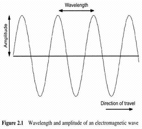
Another fundamental characteristic of an electromagnetic wave is its wavelength
 
The wavelength of a periodic sine save is shown in Figure 2.1

figure 2.5
 
The wavelengthλ and frequency f of an electromagnetic wave are related to the following equation : c = λf where c is a constant representing the speed of light

BackToTop
2.2.1 Transmission Bands and their Characteristics
 
 
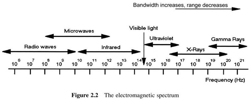
The complete range of electromagnetic radiation is known as the electromagnetic spectrum, it comprises a number of parts called bands
 
There is not a clear distinction between some bands of the electromagnetic spectrum
 
This can be seen in Figure 2.2, which shows the electromagnetic spectrum and its classification into several bands

figure 2.2
 
As can be seen from the figure, frequency is measured on a logarithmic scale
 
Thus, higher bands have more bandwidth and can carry more data, however the bands above visible light are rarely used in wireless communication systems
 
Another difference between spectrum bands relates to the attenuation they suffer
 
Higher frequency signals typically have a shorter range than lower frequency signals as higher frequency signals are more easily blocked by obstacles
 
The various bands of the spectrum are briefly summarized below in increasing order of frequency
 
Radio : radio waves occupy the lowest part of the spectrum
 
Modern wireless communication systems favor the use of high frequency radio bands for fast data services while lower frequency radio bands are limited to TV and radio broadcasting
 
The Long Wavelength(LW), Very High Frequency(VHF) and other portions of the radio band of the spectrum are shown in Figure 2.3
figure 2.6
 
Microwaves : the high frequency radio bands (UHF, SHF and EHF) are referred to as microwaves
 
Microwaves have a large number of applications in wireless communications which stem from their high bandwidth
 
However, they have the disadvantage of being easily attenuated by objects found in their path
 
The commonly used parts of the microwave spectrum are shown in Figure 2.4
figure 2.7
 
Infrared(IR) : IR radiation is located below the spectrum of red visible light
 
Such rays are emitted by very hot objects and the frequency depends on the temperature of the emitting body
 
It also find use in some wireless communication systems, an example is the infrared-based IEEE 802.11 WLAN
 
Visible light : the tiny part of the spectrum between UV and IR in Figure 2.4 represents the visible part of the electromagnetic spectrum
 
Ultraviolet(UV) : such rays can be produced by the sun and ultraviolet lamps, it is also dangerous to humans
 
X-Rays : X-Rays, also known as Roentgen rays, are characterized by shorter frequency than gamma rays.
 
X-Rays are also dangerous to human health as they easily penetrate body cells
 
Gamma rays : these kinds of radiation carries very large amounts of energy and are usually emitted by radioactive material

BackToTop
2.2.2 Spectrum Regulation
 
 
The fact that wireless networks do not use specific mediums for signal propagation means that the wireless medium can essentially be shared by arbitrarily many systems
 
The spectrum needs to be regulated in a manner that ensures limited interference
 
Regulation is commonly handled inside each country by government-controlled national organizations
 
An international organization responsible for worldwide spectrum regulation is the International Telecommunications Union(ITU)
 
For spectrum regulation purposes, the ITU splits the world into three parts : (i) the American continent (ii) Europe, Africa and the former soviet union (iii) the rest of Asia and Oceania
 
Every couple of years the ITU holds a World Radio communication Conference(WRC) to discuss spectrum regulation issues by taking into account industry and consumer needs as well as social issues
 
Until now, three main approaches for spectrum licensing have been used : comparative bidding, lottery and auction

BackToTop
2.2.2.1 Comparative Bidding
 
 
This is the oldest method of spectrum licensing
 
Each company that is interested in becoming an operator forms a proposal that describes the types of services it will offer
 
However, the problem with this method is the fact that government-controlled national regulators may not be completely impartial and may favor some companies over others due to political or economic reasons
 
Comparative bidding is not thought to be a popular method for spectrum licensing nowadays

BackToTop
2.2.2.2 Lottery
 
 
This method aims to alleviate the disadvantages of comparative bidding
 
Potential operators submit their proposals to the regulators, which then give licenses to applicants that win the lottery
 
However, it has the disadvantage that public interest is not taken into account

BackToTop
2.2.2.3 Auction
 
 
This method is based on the fact that spectrum is a scarce, and therefore expensive, resource
 
Auctioning essentially allows governments to sell licenses to potential operators
 
In order to sell a specific license, government issues a call for interested companies to join the auction and the company that makes the highest bid gets the license
 
Although expensive to companies, auction provides important revenue to government and forces operators to use the spectrum as efficiently as possible
 
Despite being more efficient than comparative bidding and lotteries, auction also has some disadvantages, the high prices paid for spectrum force companies passed on high charges to the consumers

BackToTop
2.3 Wireless Propagation Characteristics and Modeling
 

BackToTop
2.3.1 The Physics of Propagation
 

BackToTop
2.3.1.1 Free Space Path Loss
 
 
This accounts for signal attenuation due to distance between the transmitter and the receiver
 
In free space the received power is proportional to r-2, where r is the distance between the transmitter and the receiver

BackToTop
2.3.1.2 Doppler Shift
 
 
Station mobility gives rise to the phenomenon of Doppler shift
 
A typical example of this phenomenon is the change in the sound of an ambulance passing by
 
Doppler shift is caused when a signal transmitter and receiver are moving relative to one another
 
This phenomenon becomes important when developing mobile radio system

BackToTop
2.3.1.3 Propagation Mechanisms and Slow/Fast Fading
 
 
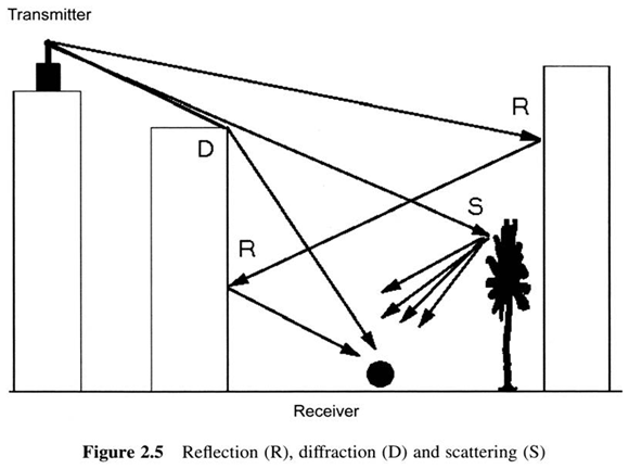
As mentioned above, electromagnetic waves generally experience three propagation mechanisms : reflection, scattering and diffraction
 
Reflection occurs when an electromagnetic waves falls on an object with dimensions very large compared to the wave’s wavelength
 
Scattering occurs when the signal is obstructed by objects with dimensions in the order of the wavelength of the electromagnetic waves
 
Diffraction, also known as shadowing, occurs when an electromagnetic waves falls on an impenetrable object
 
In this case, secondary waves are formed behind the obstructing body despite the lack of line-of-sight(LOS) between the transmitter and the receiver
 
Reflection, scattering and diffraction are shown in Figure 2.5

figure 2.5
 
In a wireless channel, the signal from the transmitter may be reflected from objects resulting in echoes of the signal propagating over different paths with different path lengths
 
This phenomenon is known as multipath propagation and can possibly lead to fluctuations in received signal power
 
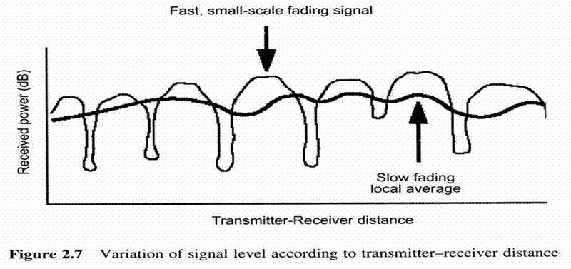
Because these small-scale fluctuations are experienced over very short, multipath fading is also referred to either as fast fading or small-scale fading
 
When a LOS exists between the receiver and the transmitter, this kind of fading is known as Ricean fading
 
When a LOS does not exist, it is known as Rayleigh fading
 
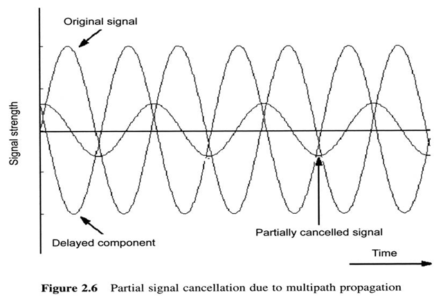
These fluctuations are due to the fact that the echoes of the signal arrive with different phases at the receiver and thus their sum behaves like a noise signal
 
When the path lengths followed by echoes differ by a multiple of half of the signal’s wavelength, arriving signals may partially or totally cancel each other
 
Partial signal cancellation at the receiver due to multipath propagation is shown in Figure 2.6
 
Despite the rapid small-scale fluctuations due to multipath propagation, the average received signal power, which is computed over receiver movements of wavelengths and used by the mobile receiver in roaming and power control decisions, is characterized by very small variations in the large scale, as shown in Figure 2.7
figure 2.6
figure 2.7

BackToTop
2.3.2 Wireless Propagation Modeling
 
 
In a wireless system, the actual signal arriving at a receiver is the sum of components that derive from several difficult to predict propagation phenomena
 
Thus, the need for a model that predicts the signal arriving at the receiver arises
 
Empirical models describe the radio characteristics of an environment based on measurements made in several other environments
 
An obvious advantage of empirical models is the fact that they implicitly take into account all the factors that affect signal propagation albeit these might not be separately identified
 
However, the accuracy of empirical models is affected by the accuracy of the measurements that are used
 
Theoretical models base their predictions not on measurements but on principles of wave theory
 
Theoretical models are independent of measurements in specific environments and thus their predictions are more accurate for a wide range of different environments
 
However, their disadvantage is the fact that they are expressed by algorithms that are very complex and thus computationally inefficient
 
For that reason, theoretical models are often used only in indoor and small outdoor areas
 
In terms of the radio environment they describe, propagation models can be categorized into indoor and outdoor models
 
Outdoor models are subdivided into macrocell models describing propagation over large outdoor areas and microcell models describing propagation over small outdoor areas

BackToTop
2.3.2.1 Macrocells
 
 
A macrocells is considered to be a relatively large area that is under the coverage of a BS
 
Macrocells were the basis for organization of the first generation of cellular systems
 
As a result, the need to predict the received signal power arose first for macrocells
 
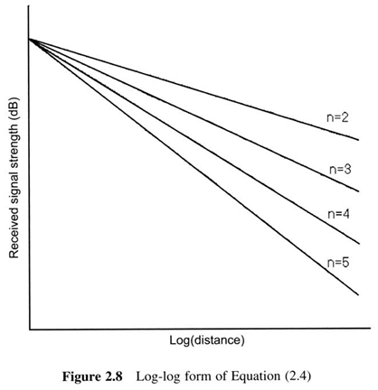
In real situation a good estimator for the received signal strength P(r) for a distance r between the transmitter and the receiver is given by P(r) = kr-n (2.4)
 
While values of n between 2 and 4 are used for modeling macrocells, the form of Equation (2.4) in a log-log scale is shown in Figure 2.8
 
The same power law model also applies to path loss, thus the average path loss at a distance r is (in dB)2 PL(r) = PL(r0) + 10nlog(r / r0) + X (2.6)

figure 2.8

BackToTop
2.3.2.2 Microcells
 
 
Microcells cover much smaller regions than macrocells, propagation in microcells differs significantly from that observed in macrocells
 
The smaller area of a microcell results in smaller delay spreads
 
Microcells are most commonly used in densely populated areas such as parts of a city
 
The model of Equation (2.6) also describes path loss in microcells, with a typical r0 value of 100m
 
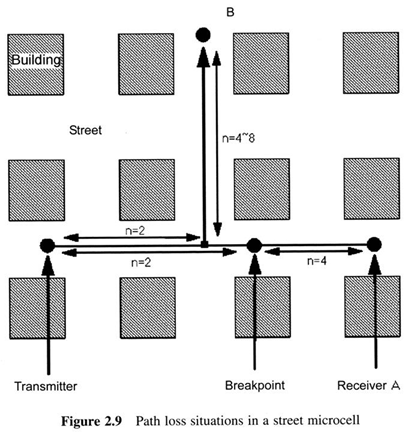
Andersen et al. mention the concept of a ‘street microcell’, which is shown in Figure 2.9
 
This kind of microcell is created by placing transmitter antennas lower than surrounding buildings
 
Thus, most of signal power propagates along streets, even in this case nearby buildings play an important role regarding received signal quality
 
Assuming the situation of a street microcell that has the form of a grid comprising square buildings, there exist two possible situations :
 
If a LOS exist between the transmitter and the receiver (e.g. receiver A in 2.9) then the path loss model comprises two parts
 
Up to a certain breakpoint, the exponent n is around 2, as in free-space loss
 
However, beyond this breakpoint the signal strength decreases more steeply with a value of n around 4
 
If a LOS does not exist between the transmitter and the receiver (e.g. receiver A in 2.9), then the path loss is greater for the receiver
 
Up to the intersection of the two streets , the exponent n is around 2, however beyond the intersection n takes values between 4 and 8

figure 2.9

BackToTop
2.3.2.3 Indoor propagation and its differences to outdoor propagation
 
 
Indoor propagation has attracted significant attention due to the rising popularity of indoor voice and data communication systems, such as WLANs, cordless telephones, etc
 
Although the phenomena that govern indoor propagation are the same as those that govern outdoors, there are several differences between indoor and outdoor environments :
 
Dependence on building type : radio propagation is more difficult to predict in indoor environments and on a number of factors relating to the building
 
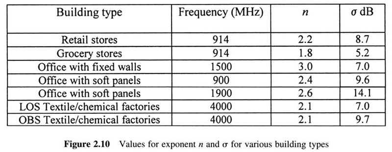
Inside buildings, two types of transmitter/receiver path exist, based on whether the transmitter is visible to the receiver: LOS paths and obstructed (OBS) paths
 
Building types are summarized in Figure 2.10

figure 2.10
 
Delay spread : inside a building, objects that cause scattering are usually located much closer to the direct propagation path between the transmitter and the receiver
 
Thus, delay spread due to multipath propagation is typically smaller in indoor systems
 
Propagation between floors : typically, there will be a reuse of frequencies between different floors of a building in an effort to increase spectrum efficiency
 
Thus, inter-floor interference will significantly depend on the inter-floor propagation characteristics
 
This makes prediction of propagation between floors an important factor
 
Although this problem is quite difficult some general rules exist:
   
(a)the type of material that separates floors impacts signal attenuation between the floors
   
(b)buildings with a square footprint induce greater attenuation than buildings with a rectangular footprint due to signals traveling between floors
   
(c)the greatest path loss of a signal crossing floors occurs when the signal passes from the originating floor to an adjacent one
 
Outdoor to indoor signal penetration : indoor environments are often affected by signals originating from other buildings or outdoor systems
 
Is appears that outdoor to indoor signal attenuation decreases for the higher floors of a building
 
This is due to the fact that at such floors a LOS path with the antenna of the outdoor system may exist

BackToTop
2.3.3 Bit Error Rate(BER) Modeling of Wireless Channels
 
 
Although there are a number electromagnetic wave propagation impairments, such as free-space loss and thermal noise, fading is the primary cause of reception errors in wireless communications
 
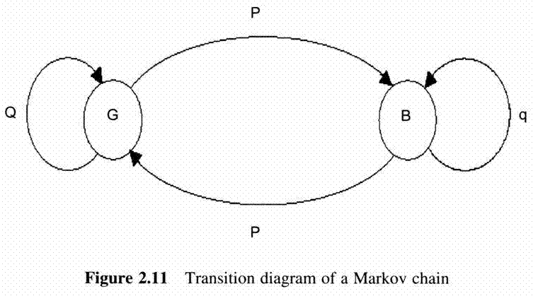
In contrast to the random nature of bit error occurrence in wired channels, bit errors over wireless channels occur in bursts and Markov chain model approximations have been shown to be adequate for wireless channel bit error modeling
 
Such models comprise two states, a good (G) and a bad (B) state
 
Figure 2.11 depicts the transition diagram of a Markov chain
 
P is the probability of the channel state transiting from state G to state B, p defines the probability of transition from state B to state G, Q = 1 – P, q = 1 - p

figure 2.11

BackToTop
2.4 Analog and Digital Data Transmission
 
 
An important parameter of message relaying between a source and a destination is whether the message is analog or digital
 
These term relate to the nature of the message and can characterize either the transmitted data or the form of the the actual signal used to carry the message
 
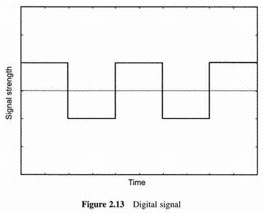
Analog and digital signal representations are shown in Figures 2.12 and 2.13
 
The difference is obvious : analog signals take continuous values in time whereas digital ones change between certain levels at specific time positions

figure 2.13
figure 2.14
 
The vast majority of the early radio communication systems concerned sound transmission
 
Television transmission comprises two analog components, corresponding to sound and image
 
However, modern wireless systems are increasingly being used for computer data communications, such as file transfer
 
There is a trend towards digital representation of analog data, which stems from the inherent advantage of digital over analog technology
 
Above advantage are briefly summarized below :
 
Transmission reliability :transmission of a message through a medium is generally degraded by noise, the digital representation of a message increases the tolerance of a wireless system to noise
 
Efficient use of spectrum :the above mentioned increased noise tolerance of digital representation helps increase the amount of information that can be transmitted using a wireless channel
 
Security : digital data can be easily and efficiently encrypted even up to a point that makes unauthorized decryption of the message almost impossible

BackToTop
2.4.1 Voice Coding
 
 
While the trend in modern wireless networks is towards data communications, the demand for voice-related services such as traditional mobile phone calls is expected to continue to exist
 
Thus voice needs to be converted from its analog form to a digital form that will be transmitted over the digital wireless network
 
The device that perform this operation are known as codecs (coder/decoder) and have been used mainly in mobile phones
 
A codec can convert an analog speech signal to its digital representation by sampling the analog signal at regular time intervals
 
This method is known as Pulse Code Modulation(PCM) and is used in codecs of PSTN and CD systems
 
There is a direct relationship between the number of samples per second, W, and the width, H, of the analog signal we want to digitize
 
This is give in the following equation : W = 2H bps
 
The process of PCM conversion of an analog signal to a digital one comprises three stages :
 
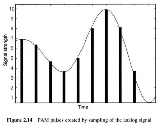
Sampling of the analog signal :this produces a series of samples, known as Pulse Code Modulation(PCM) pulses, with amplitude proportional to the original signal
 
The PAM pulses produced after sampling of an analog signal are shown in Figure 2.14

figure 2.15
 
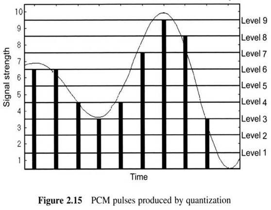
Quantizing : this is essentially the splitting of the effective amplitude range of the analog signal to V levels which are used for approximating the PAM pulses
 
These V levels are selected as the median values between various equally spaced signal levels
 
The quantization of the PAM pulses of Figure 2.14 is shown in Figure 2.15
figure 2.16
 
Binary encoding : this is encoding of the quantized values of PAM to binary format, which forms the output of the PCM system and will be used to modulate the signal to be transmitted
 
PCM demands relatively high bit rates and is thus not very useful for wireless communications systems, such as mobile phones

BackToTop
2.4.1.1 Vocoders and hybrid codecs
 
 
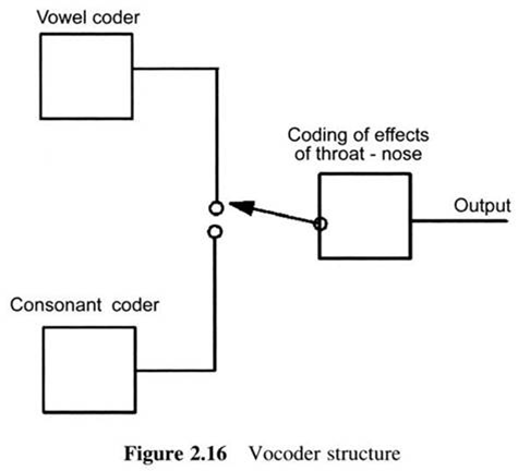
In an effort to reduce the bit rate required for voice transmission, engineers have exploited the actual structure and operation of human speech production organs and the devices that work based on this are known as vocoders
 
Vocoders, which were initially only an attempt to synthesize speech , work by encoding not the actual voice signals but rather by modeling the mechanics of how sounds are produced
 
A simple vocoder diagram is shown in Figure 2.16, it comprises three parts : the part responsible for coding vowel sounds, which are attributed to the vocal cords the part responsible for coding consonant sounds, which are produced by lips, teeth, etc the part that is responsible for coding the effects of the throat and nose on the speech signal

figure 2.1
 
Vocoders are very useful since they achieve voice transfer with a low bit rate
 
However, the voice produced is not very ‘natural’ and has a somewhat ‘artificial’ quality
 
In some cases it is even difficult to tell who is actually speaking
 
Hybrid codecs try to overcome this problem by transmitting both vocoding and PCM voice information while also making sure that sounds that are inaudible to the human ear are not transmitted

BackToTop
2.5 Modulation Techniques for Wireless Systems
 
 
Whether in analog or digital format, data has to be converted into electromagnetic waves in order to be sent over a wireless channel
 
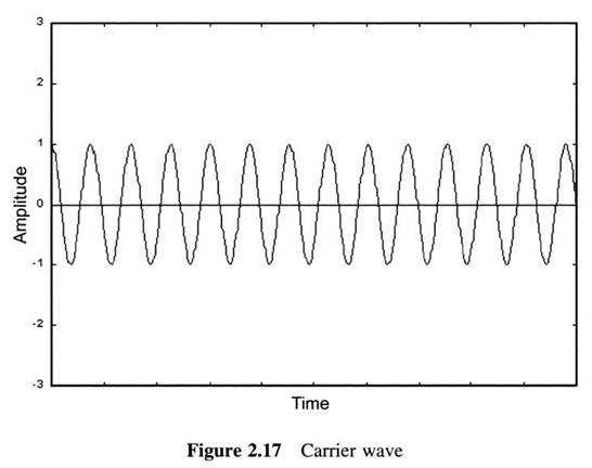
The techniques used to perform this are known as modulation techniques and operate by altering certain properties of a radio wave, known as the carrier wave, which has the frequency of the wireless channel used for communication
 
The nature of the data to be transmitted, directly impacts the output of modulation

BackToTop
2.5.1 Analog Modulation
 
 
In order for analog data to be transmitted, analog modulation techniques are used
 
Analog modulation works by impressing the analog signal containing the data on a carrier wave
 
The most well known analog modulation techniques are Amplitude Modulation(AM) and Frequency Modulation(FM)

BackToTop
2.5.1.1 Amplitude Modulation(AM)
 
 
The modulated signal s(t) is thus produced by adding s(t) to the product of s(t) and x(t)
 
Mathematically, AM is expressed by the following equation : s(t) = (1 + x(t))cos(2πft)
 
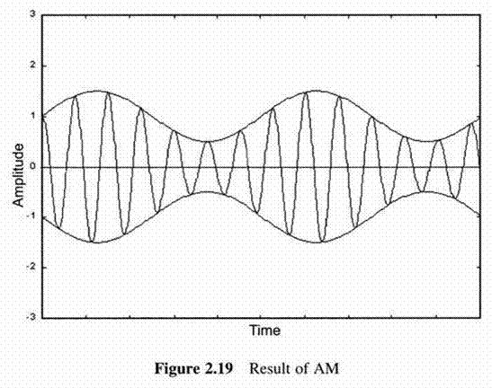
AM results in a wave of an amplitude varying according to the amplitude of the analog information signal x(t)
 
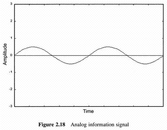
Figures 2.17-2.19 show a carrier wave of amplitude twice that of the analog information signal

figure 2.17
figure 2.18
figure 2.19
 
From Figure 2.19 one can see that the analog information signal can be easily decoded at the receiver by ‘following’ either the positive or negative peaks of the AM signal
 
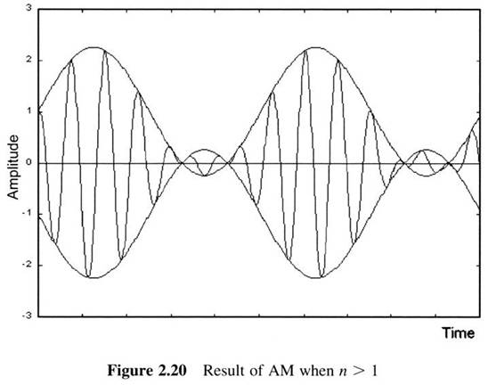
However, this is not possible in cases where the ratio n of the maximum amplitude of the information signal x(t) to that of the carrier c(t) is higher than 1
 
In this case, decoding is more difficult, as ‘following’ either the positive or negative peaks of the amplitude-modulated signal does not give x(t) but rather its absolute value, |x(t)|
 
Thus, the information signal is received distorted
 
This is shown in Figure 2.20, which depicts the AM signal produced by modulating the carrier wave of Figure 2.17 with an analog signal having twice the amplitude of the carrier
figure 2.20

BackToTop
2.5.1.2 Frequency Modulation(FM)
 
 
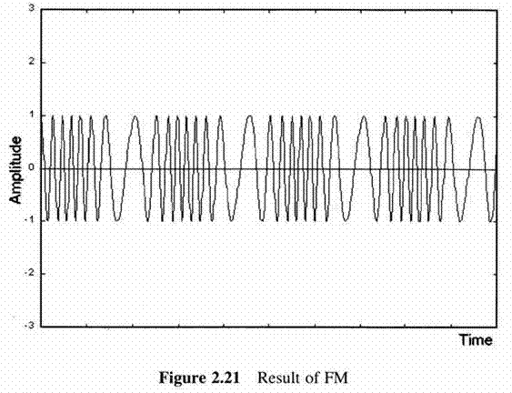
In FM, the information signal is used to alter the frequency of the carrier wave rather than its amplitude
 
This makes FM more resistant to noise than AM, since most of the times noise affects the amplitude of a signal rather than its frequency
 
FM can be expressed mathematically as :

 
Figure 2.21 shows the output signal of FM for the carrier wave and information signal shown in Figures 2.17 and 2.18
 
Apart from conventional analog radio broadcasting, known to most people as FM radio, FM is used in first generation cellular systems, like the AMPS standard
figure 2.21

BackToTop
2.5.2 Digital Modulation
 
 
Digital modulation techniques work by converting a bit string to a suitable continuous time waveform
 
The most popular digital modulation techniques are amplitude Shift Keying(ASK), two level (binary) and four-level Frequency Shift Keying(FSK), Phase Shift Keying(PSK) and its variants

BackToTop
2.5.2.1 Amplitude Shift Keying(ASK)
 
 
The output of ASK for transmission of a binary string x, works as follows
 
Transmission of a binary 1 is represented by the presence of a carrier for a specific time interval, whereas transmission of a binary 0 is represented by a carrier absence for the same interval
 
Thus, for a cosine carrier of amplitude A and frequency f, we have

 
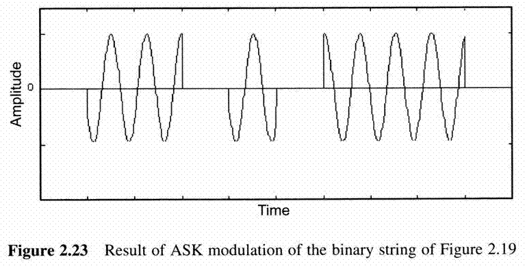
The result of ASK modulation of the binary string of Figure 2.22 using the carrier of Figure 2.17, is shown in Figure 2.23
figure 2.22
figure 2.23

BackToTop
2.5.2.2 Frequency Shift Keying (FSK)
 
 
The output of FSK for transmission of a binary string x, works as follows
 
Assuming a carrier of frequency f and a small frequency offset k, transmission of a binary 1 is represented by the presence of a carrier of frequency f + k for a specific time interval, whereas transmission of a binary 0 is represented by a carrier of frequency f – k for the same interval
 
Thus for a cosine carrier of amplitude A and frequency f, we have

 
Since two frequency levels are used , this technique is also known as two-level or binary FSK(BFSK)
 
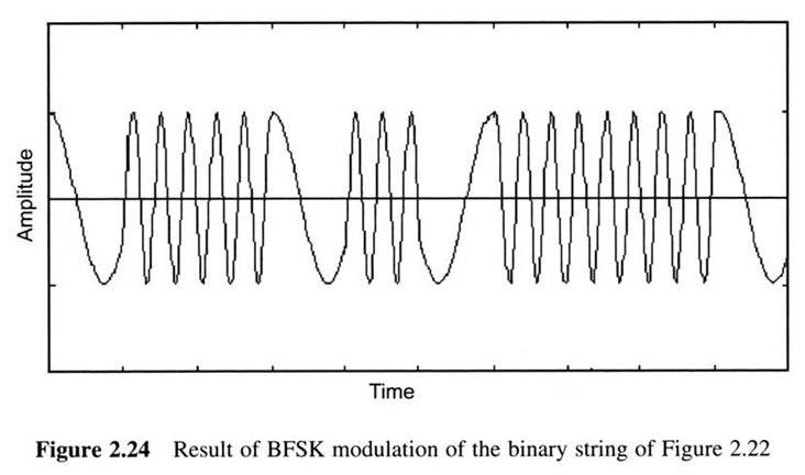
The result of BFSK modulation of the binary string of Figure 2.23 using the carrier of Figure 2.17 is shown in Figure 2.24
 
In BFSK, every frequency shift encodes one bit
 
By defining more offsets for the frequency deviation, FSK can transmit more information with a single frequency shift
figure 2.24
 
For example, four-level FSK:
can transmit two bit per frequency shift
 
FSK is used in a number of wireless communication systems

BackToTop
2.5.2.3 Phase Shift Keying(PSK)
 
 
The output of PSK for transmission of a binary x, works as follows
 
Assuming a carrier of frequency f , transmission of a binary 0 is represented by the presence of the carrier for a specific time interval, whereas transmission of a binary 1 is represented by the presence of the carrier signal with a phase difference of πradians, for the same interval
 
For a cosine carrier of amplitude A and frequency f, we have

 
Since a single phase difference, this technique is also known as two-level or binary PSK(BPSK)
 
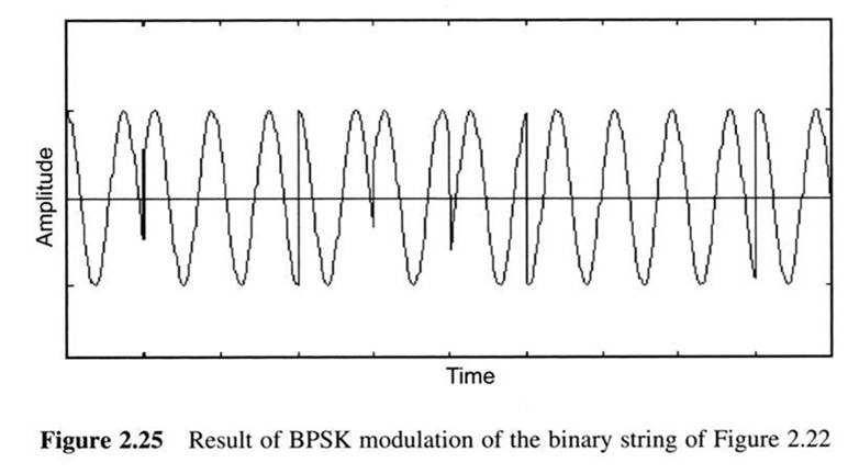
The result of BPSK modulation of the binary string of Figure 2.22 using the carrier of Figure 2.17 is shown in Figure 2.25
 
In BPSK, every phase representation encodes one bit
figure 2.25
 
A number of techniques exist that are essentially PSK variations :
 
Differential PSK(DPSK) : this is a variant of PSK
 
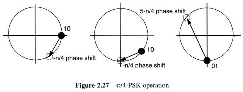
π/ 4-shifted PSK : this is another four-level PSK technique that provides self-clocking
 
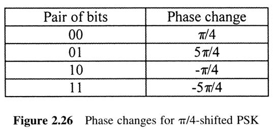
π/ 4-shifted PSK codes pairs of bits by varying the phase of the carrier relative to the phase of the carrier used for the preceding pair of bits, according to figure 2.26
figure 2.26
 
Is can easily be seen that there is always a phase change between consecutive bit transmissions
 
This can be seen for the transmission of 101001 in Figure 2.27
figure 2.27
 
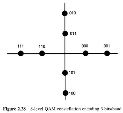
Quadrate Amplitude Modulation (QAM) : in QAM both the amplitude of the carrier and its phase are altered
 
Taking for example QPSK and assuming that we are able to code the four different phases with two different amplitude values, we have eight different combinations which can effectively code three bits per sample
 
For various QAM schemes these sets of combinations are known as constellation patterns
 
The constellation pattern for the system mentioned above is shown in figure 2.28
figure 2.28

BackToTop
2.6 Multiple Access for Wireless Systems
 
 
As in all kinds of networks, nodes in a wireless network have to share a common medium for signal transmission
 
Multiple Access Control(MAC) protocols are algorithms that define the manner in which the wireless medium is shared by the participating nodes
 
MAC protocols for wireless networks can be roughly divided into three categories : Fixed assignment(TDMA, FDMA), random access (ALOHA, CSMA/CA) and demand assignment protocols(polling)

BackToTop
2.6.1 Frequency Division Multiple Access(FDMA)
 
 
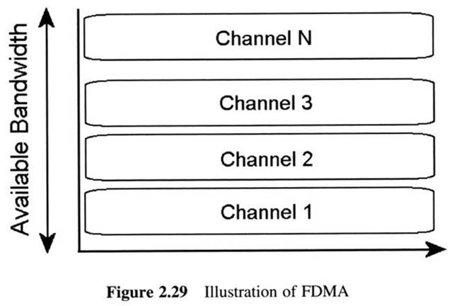
In order to accommodate various nodes inside the same wireless network, FDMA divides the available spectrum into subbands each of which are used by one or more users
 
FDMA is shown in Figure 2.29
 
Using FDMA, each user is allocated a dedicated channel, different in frequency from the subbands allocated to other users
 
Over the dedicated subband the user exchanges information

figure 2.29
 
In cellular systems, channel allocations typically occur in pairs
 
Thus, for each active mobile user, two channels are allocate, one for the traffic from the user to the BS and one for the traffic from the BS to the user
 
The frequency of the first channel is known as the uplink (reverse link) and that of the second channel is known as the downlink(forward link)

Due to the fact that pairs of uplink/downlink channels are allocated by regulation agencies, most of the time they are of the same bandwidth

 
This makes FDMA relatively inefficient since in most systems the traffic on the downlink is much heavier than that in the uplink
 
The biggest problem with FDMA is the fact that channels cannot be very close to one another
 
It is because transmitters that operate at a channel’s main band also output some energy on sidebands of the channel
 
Thus, the frequency channels must be separated by guard bands in order to eliminate inter-channel interference
 
The existence of guard bands, however, lowers the utilization of the available spectrum, as can be seen in Figure 2.30 for the first generation AMPS and Nordic Mobile Telephony (NMT) systems
figure 2.30

BackToTop
2.6.2 Time Division Multiple Access (TDMA)
 
 
In TDMA, the available bandwidth is shared in the time domain, rather than in the frequency domain
 
TDMA is the technology of choice for a wide range of second generation cellular systems such as GSM, IS-54, and DECT
 
TDMA divides a band into several time slots and the resulting structure is known as the TDMA frame
 
Uplink and downlink channels in TDMA can either occur in different frequency bands (FDD-TDMA) or time-multiplexed in the same band (TDD-TDMA)
 
The latter technique obviously has the advantage of easy trading uplink to downlink bandwidth for supporting asymmetrical traffic patterns
 
Figures 2.31 and 2.32 show the structure of FDD-TDMA and TDD-TDMA
 
TDMA is essentially a half-duplex technique, since for a pair of communicating nodes, at a specific time, only one of the nodes can transmit

figure 2.31
figure 2.32
 
Dynamic TDMA schemes allocate slots to nodes according to traffic demands,they have the advantage of adaptation to changing traffic patterns
 
Three such schemes are outlined below :
 
The first scheme is assumed that the number of stations is lower than the number of slots, thus each station can be assigned a specific slot
 
The second scheme is assumed that the number of stations is unknown and can be variable
 
The third scheme tries to minimize the bandwidth loss due to collisions

BackToTop
2.6.3 Code Division Multiple Access(CDMA)
 
 
The third medium access technique, CDMA, instead of sharing the available bandwidth either in frequency or time, it places all nodes in the same bandwidth at the same time
 
The transmission of various users are separated through a unique code that has been assigned to each user
 
CDMA has its origins in spread spectrum, the propose of spread spectrum was to avoid jamming or interception of narrowband communications by the enemy
 
This form of spread spectrum is known as Frequency Hopping Spread Spectrum(FHSS) and although not used as a MAC technique, it has found application in several systems
 
CDMA is often used to refer to the second from of spread spectrum, Direct Sequence Spread Spectrum(DSSS), which is used in all CDMA-based cellular telephony systems
 
All nodes are assigned a specific n-bit code
 
The value of parameter n is known as the system’s chip rate
 
The various codes assigned to nodes are orthogonal to one another, meaning that the normalized inner product of the vector representations of any pair of codes equals zero
 
CDMA has found application in several systems as a method of combating multipath interference
 
Such a situation is the use of CDMA as an option for transmission the physical layer of IEEE 802.11 WLAN
 
An example of CDMA is shown in Figure 2.33
 
CDMA makes the assumption that the signals of various users reach the receiver with the same power
 
However, in wireless systems this is not always true
 
Due to the different attenuation suffered by signals following different propagation paths, the power level of two different mobiles may be different at the BS of a cellular system
 
This is known as the near-far problem and is solved by properly controlling mobile transmission power

figure 2.33

BackToTop
2.6.4 ALOHA-Carrier Sense Multiple Access(CSMA)
 
 
The ALOHA protocol is related to one of the first attempts to design a wireless network
 
It was the MAC protocol used in the research project ALOHANET, the idea of the project was to offer bi-directional communications without the use of phone lines between computers spread over four islands and central computer
 
The principle of ALOHA is fairly simple : whenever a station has a packet to transmit, it does so instantaneously
 
A critical point is the performance of ALOHA
 
One can see that in order for a packet to reach the destination successfully, it is necessary that :
 
No other transmission begin within one frame time of its start
 
No other transmissions are in progress when the station starts its own transmission, this is because stations in ALOHA do not check for other transmissions before they start their own
 
The throughput Ts(S) for an offered load of G frames per frame time in a slotted ALOHA system that uses frames of fixed size is given by Ts(S) = Ge-G
 
The obvious advantage of ALOHA is its simplicity, however, this simplicity causes low performance of the system
 
Carrier Sense Multiple Access(CSMA) is more efficient than ALOHA
 
A CSMA station that has a packet to transmit listens to see if another transmission is in progress, if this is true, the station defers
 
The behavior at this point defines a number of CSMA variants :
   
P-persistent CSMA
   
Nonpersistent CSMA
 
Of course, if more than two stations want to transmit at the same time, they will all sense the channel simultaneously
 
If they find it idle and some decide to transmit, a collision will occur and the corresponding frames will be lost
 
However, it is obvious that collisions in a CSMA system will be less than in an ALOHA system, since in CSMA stations ongoing transmissions are not damaged due to the carrier sensing functionality
 
CSMA has found use in wireless network, especially WALNs
 
In wired networks, CSMA is the basis of the IEE802.3 protocol, known to most of us as Ethernet

BackToTop
2.6.5 Polling Protocols
 
 
Polling protocols are centralized. For a polling protocol to be applied, a central entity (Base Station, BS) is assigned responsibility for polling the stations within the network.
 
If the BS decides that a specific station grants permission to transmit, it polls this station, meaning that it sends to the station a small control frame notifying it that it can transmit one or more frames
 
Polling is an appealing MAC option, however, it demands that the BS possesses knowledge regarding the network topology in order for the network nodes to be polled.
 
In this section, we present the Randomly Addressed Polling (RAP) and Group RAP (GRAP) protocols [10-12], which were designed for Wireless LANs (WLANs) as an example.
 
RAP combats the imprecise knowledge regarding the network topology by working, not only with all the nodes under the coverage of the BS, but only with the active ones seeking uplink communication.
 
The operation of RAP constitutes a number of polling cycles.
 
When a collision between two or more" stations-occurs, these stations keep the collided compete, for access to the medium in the next polling cycle.
 
Newly, active stations are usually not allowed to compete with those having collided packets.
 
The collision resolution cycle (CRC) is defined as the period of time that elapses in order for all the active stations at the beginning of the CRC to transmit their packets.
 
In order to keep newly active nodes from entering the competition, the READY message at the beginning of a CRC can have a different form from that at the beginning of a polling cycle commencing inside a CRC.
 
For a RAP WLAN consisting of N active stations, the stages of the protocol are as follows:
 
Contention invitation stage
 
Contention stage
 
Polling stage
 
If a BS successfully receives a packet from a mobile node, it sends a positive acknowledgement (PACK). If reception of the packet at the BS is unsuccessful either due to noise or a collision, the BS informs the mobile node by sending a negative acknowledgment (NACK).
 
Figure 2.34 shows an example of RAP operation with N = 7 active stations and P =5 available random addresses
 
Comparisons with CSMA show that although the mean delay in RAP also rises rapidly under heavy load, RAP is characterized by smaller delays for a given throughput value.
 
Moreover, by increasing the value of P, the delay reduces significantly.
 
A critical point for RAP seems to be the choice of P. Use of large values of P favor performance but also lead to increased circuit complexity.

figure 2.34
 
A modification of RAP, Group RAP is proposed
 
GRAP adopts the super-frame structure, consisting of P + 1 frames and divides active nodes into groups.
 
At the beginning of each frame only the BS is allowed to transmit. After the BS completes transmission the polling procedure begins.
 
However, GRAP does not allow all active nodes to compete in a single contention period.
 
GRAP states that all nodes that successfully transmitted during the previous polling cycles maintain their random addresses and form the groups from 0 to P — 1
 
An advantage of GRAP over RAP is that it allocates much more bandwidth to the BS
 
A problem with RAP is that, if the number of active stations N approaches or exceeds P, then the performance of RAP degrades sharply
 
As a result, the probability of a successful transmission is lowered, which leads to the decreased throughput and increased delay.
 
TDMA-based RAP (TRAP) solves this problem.
 
TRAP employs a variable length TDMA-based contention stage, which lifts the requirement for a fixed number of random addresses.
 
The TDMA-based contention stage comprises a variable number of slots, with each slot corresponding to a random address.
 
However, a mechanism is needed in order for the base station to select the appropriate number of slots in the TDMA contention stage
 
Based on this approach, the proposed protocol works as follows:
 
Active stations estimation
 
Contention invitation stage
 
Contention stage
 
Polling stage
 
If a BS successfully receives a packet from a mobile node, it sends a positive acknowledgement (PACK). If reception of the packet at the BS is unsuccessful either due to noise or a collision, the BS informs the mobile node by sending a negative acknowledgment (NACK).
 
Under the assumption of all mobile random address transmissions reaching the base station, the protocol is collision free among data packets.
 
This is because the same random address transmission by two or more stations occurs in the same time slot resulting in a collision of the control packets and the address not being polled. Thus, the data packets do not collide.
 
This is an advantage of TRAP against the original RAP protocol
 
However, the obvious advantage of our proposed protocol is in terms of scalability
 
Furthermore, the implementation of TRAP protocol is much simpler than that of CDMA-based versions of RAP, since no extra hardware is needed for the orthogonal reception of the random addresses
 
Finally, another interesting polling MAC protocol for a wireless environment is Learning Automata-Based Polling (LEAP).
 
LEAP is designed for bursty traffic infrastructure WLANs
 
According to LEAP, the BS is equipped with a learning automaton which contains the choice probability Pk(j) for each mobile station k under its coordination
 
Before polling at polling cycle j those probabilities are normalized in the following way
 
The protocol uses four control packets, POLL,NO_DATA, BUFF_DATA and ACK whose duration is tPOLL, tNO_DATA, tBUFF_DATA and tACK
 
The poll is received at station k at time t + tPOLL + tPROP_DELAY
 
The poll is not received, at station k, k does not respond to the base station and the choice probability of k is decreased.
 
Then the base station proceeds to poll the next station at time t + tPOLL + tPROP_DELAY + tBUFF_DATA + tDATA + tACK
 
From the above discussion, it is obvious that the learning algorithm takes into account both the bursty nature of the traffic and the bursty appearance of errors over the wireless medium
 
LEAP updates the choice probabilities of mobile stations according to the network feed?back information. The choice probability of each mobile station converges to the probability that this station is ready to transmit, meaning that it has a nonempty queue and it is capable of communicating successfully with the base station

BackToTop
2.7 Performance Increasing Techniques for Wireless Network
 
 
As mentioned above, the basic problem in wireless networks is the fact that wireless links are relatively, unreliable.
 
Thus, a number of schemes that work on the physical layer and try to present a relatively 'clean' medium to higher layers of the network have been considered
 
In this section, we describe some other techniques: diversity ,coding, equalization and power control.

BackToTop
2.7.1 Diversity Techniques
 
 
In an effort to combat the phenomenon of fading in wireless channels, a family of techniques, known as diversity techniques, is used.
 
Many types of diversity techniques exist, such as time frequency, antenna (also known as space) and polarization diversity.
 
The principle of diversity systems is to send copies of the same information signal through several different channels.
 
Performance enhancement is achieved due to the fact that these channels fade independently, thus, fading will affect only a part of the transmission

BackToTop
2.7.1.1 Antenna Diversity
 
 
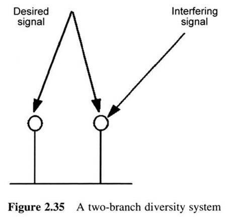
Antenna diversity, also known as space diversity is common1y used for performance enhancement in wireless systems.
 
It is essentially a method that calls for a set of array elements, mostly two, spaced sufficiently, apart from each other, with the spacing usually in the order of the wavelength of the used channel.
 
Antenna diversity can effectively combat multipath fading in NLOS situations
 
When applied at the BS of a cellular system, receive antenna diversity obviously enhances the performance of the uplink.
 
Thus, it has found use in the uplink of a number of wireless-systems, such as GSM and IS-136
 
Figure 2.35 sketches the way a two-branch receive diversity system can combat interference

figure 2.35

BackToTop
2.7.1.2 Multiantenna Transmission/Reception: Smart Antennas
 
 
The term smart antennas is used to describe antennas that are not fixed but rather change in order to adapt to the conditions of the wireless channel.
 
Smart antennas combat the deficiencies of conventional omnidirectional antennas
 
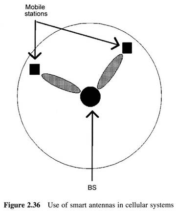
Considering the case of a cellular system, omnidirectional antennas can be regarded as a waste of power, due to the fact that they radiate power in all directions while the user being serviced by the antenna is only in a certain direction.
 
Smart antennas surpass this inefficiency since they can
   
(a) focus to the radio transmission of the receiver and
   
(b) focus their own transmission towards the receiver, as seen in Figure 2.36 for a cellular-system

figure 2.36
 
According to the principle on which beamforming is based, smart antennas can be categorized into :
 
Switched lobe, or switched beam
 
Dynamically phased array : This category utilizes information regarding the direction of arrival, of the transmitter’s signal
 
Adaptive array : This category utilizes the direction of arrival value of users nearby the entity, which transmits to the antenna
 
The above methods describe tracking of the reception signal by the BS which implements antenna diversity
 
As far as transmission to a mobile is concerned, the BS may utilize the value of direction of arrival of the mobile node transmission at the BS in order to focus its transmission on the mobile receiver.
 
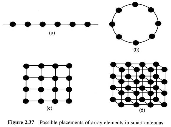
Figure 2.37 shows possible structures of array elements that form smart antennas.
 
The first two structures are used for beamforming on a horizontal plane, which is enough for large cells, typically found in rural areas.
 
For densely populated cells, the third and fourth structures can be used for two-dimensional beamforming
figure 2.37
 
Finally, when smart antennas find full application in mobile systems, these will be able to accommodate traffic from many users in the same frequency at the same time and separate users by spatial information.
 
This will create a new form of multiple access, Space Division Multiple Access (SDMA), where users will be separated based on the angle of their transmission to the base station.
 
Due to their capability for directive transmission, smart antennas have the obvious advantage of interference reduction for users nearby the receiver.
 
Furthermore, the capacity of a system is increased since it is possible that the same spectrum can be used at the same time by more than one user.
 
This can be done by exploiting information regarding their position and using smart antennas to direct BS transmissions to these users
 
However, the use of smart antennas entails some problems too.
 
The first is the increased implementation complexity and the cost of the method
 
Furthermore, the fact that SDMA separates users based on their angle to the receiver means that BSs will have to switch users to another SDMA channel when angular collisions occur
 
Nevertheless, the cost of a smart antenna system will be larger than a system with conventional antenna.

BackToTop
2.7.2 Coding
 
 
In all kinds of networks, there is a certain possibility that reception of a bit stream is altered by errors.
 
Coding techniques aim to provide resistance to such errors by adding redundant bits to the transmitted bit stream so that the receiver can either detect and ask for a retransmission, or correct the faulty reception.
 
Thus, we have error detection and error correction coding schemes, respectively.
 
The process of adding this redundant information is known as channel coding, or Forward Error Correction (FEC)

BackToTop
2.7.2.1 Parity Check
 
 
The-simplest technique which is known to almost anyone dealing with computer technology, is the parity bit technique that can detect single-bit errors
 
Although very simple to implement, the parity scheme has the disadvantages of
   
(a) not being able to detect a multiple of two bit errors in the same message and
   
(b) being able only to detect and not to correct a faulty reception

BackToTop
2.7.2.2 Hamming Code
 
 
The addition of extra bits for coding should produce a set of valid bit streams that has the maximum possible distance.
 
It holds that if coding leads to a set of valid bit streams of distance d, then it can either detect D errors or correct Terrors, where d >= D + 1 and d ? [2T + 1...2T + 2], respectively.
 
The Hamming code is very popular error correcting code with distance 3; thus T = 1
 
In the Hamming code, the number of the bits of the coded message, n, the number of the bits of the message to be coded, k, and the number of coding bits, r, are related according to the following. equations:
 
n=2r - 1, . k=2r – 1 - r (2.20)
 
A slight modification of the Hamming code permits it to correct not only one bit error but also a burst error of length s in bits
 
For coded messages of length j this is done by: coding the messages to be transmitted according to the Hamming code; gathering at least s such messages into the rows of an s 2 j matrix A; calculation of the j 2 s matrix B having they columns of matrix A as its rows (retrograde matrix); transmission of the j messages of length s as those appear in the lines of matrix B

BackToTop
2.7.2.3 Cyclic Redundancy Check (CRC)
 
 
CRC is a widely used error detecting code.
 
For the coding of an m-bit message M with n coding bits, the transmitter and receiver agree on a common (n + 1)-bit stream P, with n < m.
 
CRC codes this message by appending an n-bit sequence F, known as the Frame Check Sequence (FCS) to the end of the m-bit-message.
 
By shifting M n bits left and modulo-2 dividing the result E with P, the FCS F is defined as the remainder of this modulo-2 division
 
If there is a nonzero remainder, the message was received with an error, otherwise it is assumed correct

BackToTop
2.7.2.4 Convolutional Coding
 
 
Convolutional codes have found use in several wireless systems, such as the IS-95 cellular standard
 
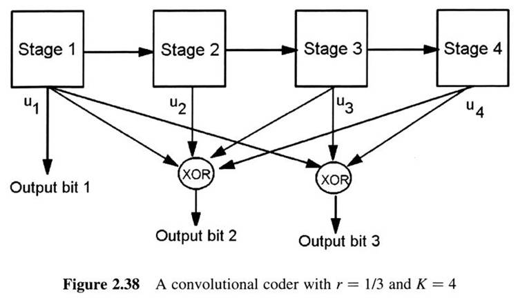
Convolutional codes are usually referred to based on the code's rate r = k/n and constraint length K.
 
The code rate of a Convolutional code shows the ratio of the number of bits n that are output of the Convolutional. encoder to the number of bits k that were fed into the encoder.
 
Convolutiortal coding of a bit stream will produce a larger bit stream
 
In general, the larger the value of K, the less probability of a bit suffering an error
 
Specifically, the value of K and this probability are exponentially related.
 
In order to gain an insight into the operation of a convolutional coder, consider the example Figure 2.38 which shows a convolutional coder with K = 4 and r = 1/3.
 
Generally, for an r code and a k-bit input stream, the number of output bits is (k + K)/r

figure 2.38
 
The operation of a convolutional coder depends on the selection for a value of K, the number of XOR adders and the way these are connected to stage outputs ui
 
Two categories of convolutional decoding algorithms exist.
 
The first is sequential decoding. It has the advantage of performing very well with convolutional codes of large K, but it has a variable decoding time.
 
The second category, Viterbi decoding, removes this disadvantage by having a fixed decoding time; however, it has an increased computational complexity, which is exponentially related to the value of K

BackToTop
2.7.3 Equalization
 
 
Equalization techniques have found wide use in wireless systems for combating the effect of LSI.
 
The general idea of equalization is to predict the ISI that will be encountered by a transmission and accordingly modify the signal to be transmitted so that the signal reaching the receiver will represent the information the transmitter wants to send.
 
Two categories of equalization techniques exist: linear and nonlinear.
 
Linear equalization techniques are not preferred for wireless communication systems
 
Nonlinear techniques, such as decision feedback equalization (DFE), data directed estimation (DDE) and maximum likelihood sequence estimation (MLSE) are commonly used for wireless systems
 
DEE employs a set of coefficients that are used for modeling the behavior of the wireless channel
 
There are many possible algorithms to compute the coefficients of an equalizer.
 
The most popular are the least mean square (LMS) and the recursive least squares (RLS)

BackToTop
2.7.4 Power Control
 
 
Power Control (PC) schemes try to minimize interference in the system and conserve energy at the mobile nodes by varying transmission power.
 
When increased interference is experienced within a cell, PC schemes try to increase the Signal to Interference noise Ratio (SIR) at the receivers by boosting transmission power at the sending nodes.
 
When the interference experienced is low, sending nodes are allowed to lower their transmitting power in order to preserve energy and lower the interference.
 
PC has a dual purpose: performance enhancement and energy preservation at the mobile nodes.
 
PC can provide substantial performance increases and, as was mentioned earlier, is useful especially in CDMA systems in order to combat the 'near-far' problem.
 
There are two fundamental types of PC schemes : Open-loop PC and Close-loop PC
 
PC schemes are most commonly considered for uses in cellular networks.
 
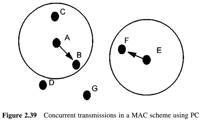
However, PC would be beneficial if taken into account during the design of MAC protocols for WLANs
 
For example, consider the case of Figure 2.39, which shows the topology of a CSMA wireless network

figure 2.39

BackToTop
2.7.5 Multisubcarrier Modulation
 
 
Multisubcarrier modulation is another technique that achieves ISI reduction.
 
The channel bandwidth is divided into N subbands.
 
A separate communication link is established over each subband.
 
The data stream is divided into N interleaved substreams, which are used to modulate the carrier of each subband.
 
This results in reduced ISI, since rnultipath fading does not occur with the same intensity over different frequency channels.
 
An example of multisubcarrier modulation is Orthogonal Frequency Division Multiplexing (OFDM)
 
OFDM has also found use as an option for transmission in the: physical layer of IEEE 802.11 (IEEE 802.11a) and is used in the physical layer of HIPERLAN 2

BackToTop
2.8 The Cellular Concept
 
 
As already mentioned, one of the basic problems in wireless networks is the fact that the spectrum is a scarce resource.
 
Apart from the techniques presented above which try to increase the capacity over a specific spectrum part, a great increase in efficient spectrum usage has been brought about with the introduction of the cellular concept
 
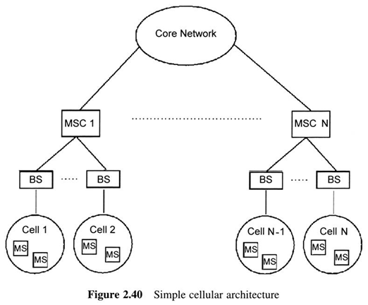
We assume the simple architecture of Figure 2.40, which comprises the following elements found in all cellular systems:
   
Mobile terminal, containing at least voice capability.
   
Base Station, which manages communications of mobile users within its cell
   
Mobile Switching Center (MSC), which controls a number of BSs and interface the cellular system to/from the core network
   
The Home Location Register (HLR) and Visitor Location Register (VLR) databases that are present in every MSC.

figure 2.40
 
Moreover, we assume presence of the following channels, which are also found in all cellular systems :
   
Broadcast. Channels, that are used to convey general control information from the BS to all mobile stations within its cell
   
Paging channels, that are used to notify a mobile station of an incoming call.
   
Random access channels, which are used by the mobile stations to initiate a call.
 
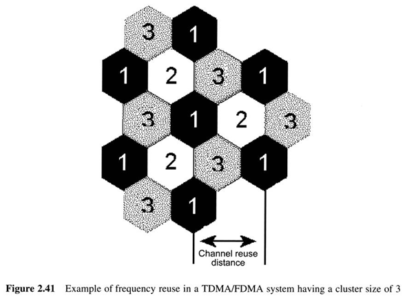
The cellular concept enables frequency reuse by stating that instead of using the same set of channels for serving the entire population of a wireless system, the geographical span of the system should be broken into pieces (cells)
 
The concept of frequency reuse using cells is illustrated in Figure 2.41, where cells are, modeled as pentagons
 
Since three different sets of cells are used, the system in Figure 2.41 is said to have a cluster size of three
figure 2.41
 
In real situations, however, larger cluster sizes seven or even twelve, are used in order to increase the distance between co-channel cells and thus reduce intercell interference.
 
The frequency reuse scheme that is achieved with the use of cells, results in an increase in overall capacity
 
Before proceeding, we explain the concept of sectorization.
 
We consider hexagonal cells divided into three sectors (spaced 120° apart).
 
Sectors within a cell use different frequencies.
 
A cluster is a set of cells. In a cluster, each frequency channel is used only once.
 
For cells having Y sectors each and K available channels, a cluster will comprise K/Y cells and the frequency reuse pattern is referred to as K/KY
 
Using the cellular approach, the effective number of channels per unit area rises, which means that the overall capacity of the system rises as well.
 
For a fixed value for the transmission power of cells’ BSs, there is a direct relationship between the frequencies used and the radius of a cell in cellular systems.
 
The use of tow frequencies can lead to higher coverage and thus less cells, which means less BSs and consequently less costs
 
This, together with the fact that people most of the time consider BSs harmful to their health, has led operators of early cellular systems assigned low frequencies to have an advantage over those assigned higher frequencies.
 
However, from the point of view of spectrum efficiency, it is advantageous to use small cells
 
When the market penetration of cellular systems was such that the need to accommodate an increased number of users became critical, this fact led operators of systems using high frequencies to have an advantage
 
The efficiency of small cells is so useful that it has led to the concept of microcells.
 
These are very small cells that are used to serve increased traffic demands in urban areas
 
Picocells, which are even smaller cells than microcells, can be deployed in very small areas such as offices or warehouses
 
So far, the discussion has implied that there is a fixed set of channels allocated to each cell
 
This strategy is also known as Fixed Channel Allocation (FCA).
 
Using FCA, channels are assigned to cells and not to mobiles nodes.
 
The problem with this strategy is that it does not take advantage of user distribution.
 
A cell may contain a few, or no mobiles nodes at all and still use the same amount of bandwidth with a densely populated cell
 
The following techniques aim to overcome this problem:
 
Borrowing channel allocation (BCA). a heavily loaded cell can ask a lightly loaded neighboring cell to let it use a number of its channels.
 
Although overcoming the aforementioned problem, BCA may introduce intra-cell inter-ference
 
Dynamic channel allocation (DCA). DCA places all available channels in a common pool and MSCs dynamically assign them to cells depending on the cells' current loads

BackToTop
2.8.1 Mobility Issue : Location and Handoff
 
 
The fundamental advantage of wireless networks is their inherent mobility.
 
In cellular systems, mobility concerns both incoming calls to mobile stations and the management of ongoing calls.
 
The first case is often referred to as the location problem.
 
When a call for a mobile terminal arrives, it is necessary that the network knows the cell where the terminal is located in order to establish the call.
 
However, since in a cellular network users may move from one cell to another (a procedure known as roaming), a mapping of terminals to cell is not possible.
 
To solve this problem, the MSCs employ the two databases mentioned above, the HLR and the VLR.
 
A different procedure takes place when the terminal moving from one cell to another is involved in a call.
 
In this situation, a procedure must be carried out that will change the BS that is involved in the call, from the BS of the old cell to the BS of the new cell.
 
This procedure is known as handoff
 
The basic principle of handoff is the following: for a specific mobile, the quality of connections to more than one BS is observed and whenever a link to a BS with quality exceeding that of the link to the current BS is found, the mobile terminal is 'handed' from the old BS to the new BS
 
The decision for a handoff can be made either by the MSCs of the network based on signal measurements made by the BSs, as is the case.in first generation cellular systems, or with the cooperation of the mobile terminal, as happens in some second generation TDMA systems
 
There are generally two types of handoff, soft and hard.
 
In soft handoff, a link is set up to the new BS before the release of the old link.
 
This ensures reliability, as the new BS may be too crowded to support the roaming mobile terminal or the link to the new BS may degrade shortly after establishment
 
Soft handoff is currently used in IS-95 CDMA-based systems.
 
Hard handoff, which is used in most cellular wireless systems, is relatively simpler than soft handoff since the link to the old BS is released before establishment of the link to the BS of the new cell.
 
However, it is somewhat less reliable than soft handoff

BackToTop
2.9 The Ad Hoc and Semi Ad Hoc Concepts
 
 
The concept of ad hoc networking is neither new, nor specific to the wireless case
 
The basic idea behind ad hoc systems stems from the early stages of Internet development, where a distributed network of peer nodes capable of operating even when a number of nodes or links are brought down or destroyed was envisioned
 
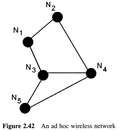
The term ‘wireless ad hoc’ stands for a network having no central administration and comprises mobile nodes that use wireless transmission.
 
As seen later, nodes in an ad hoc network can serve as routers as well, by forwarding packets between stations that are out of transmission range of one another
 
The major characteristics of ad hoc wireless networks are the following:
   
Distributed operation. An ad hoc network comprises stations that have the same capabilities and responsibility.
 
In an ad hoc network there are no BSs or MSCs and thus all network protocols operate in a distributed manner.
   
Dynamic topology. In a wireless ad hoc network, nodes are free to move in almost any possible manner.
 
The fact-that (a) some mobile stations may be out of range of one another and (b) the wireless medium condition changes rapidly over time results in dynamic network topologies with the nature of topological changes being unknown to the network a priori.
   
Multihop communications. Due to signal fading and the finite coverage of mobile transmitters, a fully connected topology connot be assumed for an ad hoc system
 
In the case where a station A need to send data to another station B out of its range, the transmission needs to be relayed through other nodes
 
Such networks are known as multihop wireless ad hoc networks
 
Changing link qualities: This is true for all wireless systems, however, it is more important in the multihop case, since the quality of a multihop path depends on the qualities of all the links that make up the path.
 
Thus, monitoring of link quality is bound to be more difficult in the multihop case.
   
Dependence an battery life. This applies to most wireless system, however, in ad hoc systems it is even more important.
 
The characteristics of dynamic topology and multihop communications make the design and operation of ad hoc systems a challenging task
 
Such systems need to operate efficiently even in cases of unknown network topologies and absence of direct paths between commu?nicating stations, which leads to multihop connections.
 
It is evident that the performance of ad hoc systems greatly depends on the efficiency of the routing scheme being used

BackToTop
2.9.1 Network Topology Determination
 
 
Ad hoc routing protocols must monitor and react to the changing network topologies.
 
Ad hoc systems may employ multihop communications, thus routing protocols must make sure that at least one path exists from any node to any other node
 
In order to efficiently monitor and adapt to changing network topologies, ad hoc routing protocols must provide all nodes with knowledge regarding their neighbors
 
Due to the distributed nature of ad hoc wireless networks, it is obvious that monitoring of network topology will be done in a distributed manner and information regarding the status of routes should be propagated to all network nodes when topology changes occur
 
Figure 2.42 shows an ad hoc network where nodes join the network one after the other, according to the corresponding numbering

figure 2.42

BackToTop
2.9.2 Connectivity Maintenance
 
 
After a network's establishment, topological changes are sure to occur either due to node mobility/failure or changing signal propagation characteristics.
 
Thus, routing protocols need to find alternative routes between stations in order to maintain connections.
 
Consider, for example, the case of the ad hoc network in Figure 2.42.
 
If nodes N3 and N1 moves so that N3 goes out of range of N1 and comes into range of N3 the topology changes to that of Figure 2.43. In this case N3 and N1 can still communicate, although only via node N2

figure 2.43
 
The performance of a wireless ad hoc system greatly depends on the routing protocol's ability to quickly
   
(a) find loop-free routes between stations when topology is changed and
   
(b) disseminate this information to all the nodes of the network
 
The application of a specific routing protocol is useful in cases when network topology changes sufficiently slowly, so that enable successful propagation of previous topology updates

BackToTop
2.9.3 Packet Routing
 
 
Routing schemes are responsible for propagating changes and compute updated routes to a destination when changes in the network topology take place.
 
In order to take into account the characteristics of wireless ad hoc networks, routing protocols for such networks employ a number of additional metrics, apart from the end-to-end throughput and delay metrics that are used in routing protocols for wired systems.
 
The main performance, metrics for wireless ad hoc network routing protocols are the following :
   
Maximum end-to-end throughput
   
Minimum end-to-end delay
   
Shortest path between communicating stations
   
Minimization of overhead due to control signaling of the routing protocols
   
Adaptability to changing topology
   
Minimization of total power consumption within the network

BackToTop
2.9.4 The Semi Ad Hoc Concept
 
 
Another wireless networking concept that is related to ad hoc is the semi ad hoc concept
 
In such a case devices can implement a dual mode of functionality, thus having the ability to operate either within a wireless network with centralized control (such as a cellular network) or within a wireless ad hoc network.
 
Whenever the entity responsible for the centralized control fails, or users move out of range of the cellular system, devices can set up an ad hoc network of their own
 
As can be seen in the corresponding chapters, most commercial ad hoc systems such as 802.11 WLANs, Bluetooth and HomeRF can follow this approach
 
Ad hoc networks are mainly used by the military whereas most commercial systems are centralized

BackToTop
2.10 Wireless Services: Circuit and Data Mode
 
 
Transmission of information, either voice or data-related, between a source and a destination station not directly connected to each other, typically employs a number of intermediate nodes.
 
The intermediate nodes are also referred to as switching nodes and the network is known as a switched network
 
Figure 2.44 shows a simple structure of a switched network, where one can see the user stations (squares) and the switching nodes (circles)

figure 2.44

BackToTop
2.10.1 Circuit Switching
 
 
In a circuit switched network, when a connection is established between two stations, the connection is assigned a dedicated sequence of links between nodes.
 
Thus in Figure 2,44, the data exchanged for a certain connection between stations A and B always follows the same path
 
In order for a data transfer to take place in a circuit switched network, the following procedures take place: Circuit establishment, Transfer of data, Circuit release
 
Circuit switching incurs on overhead for link establishment
 
However, after link establishment, the delay incurred by switching nodes is insiginificant
 
Thus, circuit switch can support isochronous services such as voice
 
This is the reason why circuit switching has been .widely utilized in cellular systems

BackToTop
2.10.2 Packet Switching
 
 
The above-mentioned problem of circuit switching for data services is solved by packet switching
 
Packet switching works by transmitting packets which most of the times are relatively small
 
Apart from the user’s data, each packet carries a control header, which contains information that the network needs to deliver the packet to its destination
 
In each switching node, incoming packets are stored and the node has to pick up one of its neighbors to hand it the packets
 
The benefits of using packet switching for data services are that bandwidth is used more efficiently, since links are not occupied during idle periods

BackToTop
2.11 Data Delivery Approaches
 
 
Data broadcasting has emerged as an efficient way for the dissemination of information over asymmetric wireless environments
 
Communication asymmetry is due to a number of facts: Equipment asymmetry, Network asymmetry, Application asymmetry
 
The goal pursued in most proposed data delivery approaches is twofold: (a) determination of an efficient sequence for data item transmissions so that the average time a client waits for an item is minimized and (b) management of the mobile clients’ local memory in a way that efficiently reduces a client’s performance degradation when mismatched occur between the client’s demands and the server’s schedule
 
Three major approaches have appeared for designing broadcast schedules, these are
 
The pull-based approach : in pull-based systems the server broadcasts information after requests made by the mobile clients via the uplink channel
 
The push-based approach : in push-based systems there is no interaction between the server and the mobile clients
 
The server is assumed to have an a priori estimate of the demand per information item and transmits data according to this estimate
 
Hybrid approaches : hybrid systems employ a combination of push and pull dividing the available downlink bandwidth into two different transmission modes

BackToTop
2.11.1 Pull and Hybrid Systems
 
 
In pull-based broadcast systems, adaptivity is trivial to implement
 
Pull systems are not easily scalable to large numbers of clients
 
In such cases, requests carried over the backchannel will either collide with each other or saturate the server

BackToTop
2.11.2 Push systems
 
 
Early push systems used the flat approach for broadcasting, which schedules all items with the same frequency.
 
The flat approach was used in the Datacycle project and the Boston Community Information System
 
A drawback of Broadcast Disks is the fact that it is constrained to fixed sized data items and does not present a way of determining either the optimal number of disks to use or their relative frequencies

BackToTop
2.11.3 The Adaptive Push System
 
 
Based on the above discussion, it would be interesting and beneficial in terms both of performance and cost, to reach a method that combines the advantages of the push and pull approaches.
 
The obvious advantage of push and pull systems are their scalability and adaptivity, respectively

BackToTop
2.12 Overview of Basic Techniques and Interactions Between the Different Network Layers
 
 
All kinds of networks, including wireless networks, are organized in a layering hierarchy
 
The most widely used layering model is the Open System Interconnection (OSI) model
 
Figure 2.45 shows the OSI reference model, which comprises 7 layers
 
The stacking of the various layers results in a hierarchy with the most intelligent layers being on the top.
 
Each layer uses services offered by the layer exactly below it

figure 2.45
 
The responsibilities of the seven layers of the OSI model, which need not be a!! implemented in network systems, are briefly summarized below:
 
The physical layer. This layer is concerned with the transmission of the information over the communications medium
 
The data link layer. The data link layer fragments large packets coming from the upper layers into several frames and ensures their correct delivery to their destination
 
The network layer. This layer is concerned with governing the operation of the network subnet
 
The transport layer. This layer is concerned with managing the connection between two end-stations
 
The session layer. This layer is concerned with managing connections between complex application processes
 
The presentation layer. This layer translates and defines the format of data to be exchanged between applications.
 
The application layer. This layer is the entry point to the OSI model and it is what a user's application sees

BackToTop Wed Mar 16 00:33:54 CST 2011 Untitled Document
First Generation Cellular Systems
3.1 Introduction
3.1.1 Analog Cellular Systems
3.1.2 Scope of the Chapter
3.2 Advanced Mobile Phone System (AMPS)
3.2.1 AMPS Frequency Allocations
3.2.2 AMPS channels
3.2.2.1 The Supervisory Audio Tone (SAT)
3.2.2.2 The Signaling Tone (ST)
3.2.3 Network Operations
3.3 Nordic Mobile Telephony (NMT)
3.3.1 NMT Architecture
3.3.2 NMT Frequency Allocations
3.3.3 NMT Channels
3.3.4 Network Operations : Mobility Management
3.3.4.1 Paging
3.3.4.2 Handover
3.3.4.3 Signal Strength Supervision
3.3.4.4 Intra-cell Handover
3.3.4.5 Handover Queue
3.3.4.6 Traffic Leveling
3.3.4.7 Location Updating
3.3.4.8 Roaming Updating
3.3.4.9 Inter-exchange Handover
3.3.4.10 Subscription Areas
3.3.5 Network Operations
3.3.5.1 Searching for a CC
3.3.5.2 Searching for a Free TC or AC
3.3.5.3 Transmission Quality supervision
3.3.5.4 Blocking of Disturbed Channels
3.3.5.5 Discontinuous Reception
3.3.6 NMT Security
3.3.6.1 Mobile Station Identity Check
3.3.6.2 Subscriber Identity Security (SIS)
3.3.6.3 Location Dependent Call Barring
3.3.6.4 PIN code

BackToTop
3.1 Introduction
 
 
The era of cellular telephony as we understand it today began with the introduc?tion of the First Generation of cellular systems
 
The use of the cellular concept greatly improved spectrum usage, for the reasons mentioned in the previous chapters.
 
However, 1G systems are now considered technologi?cally primitive
 
The reason why 1G systems are considered primitive is due to the fact that they utilize analog signaling for user traffic
 
This leads to a number of problems: no use of encryption, inferior call qualities, spectrum inefficiency

BackToTop
3.1.1 Analog Cellular Systems
 
 
United States : the first commercial analog system in the United States, known as Advanced Mobile Phone System (AMPS)
 
Europe : in European countries, several 1G systems similar to AMPS have been deployed
 
The most popular systems are TACS and NMT, which together accounted for over 50% of analog cellular subscribers in 1995
 
Japan : the first Japanese analog cellular system was the Nippon Telephone and Telegraph (NTT) system, which began operation in the Tokyo metropolitan area in 1979

BackToTop
3.1.2 Scope of the Chapter
 
 
The remainder of the chapter examines AMPS and NMT, two representative 1G cellular systems

BackToTop
3.2 Advanced Mobile Phone System (AMPS)
 
 
AMPS is a representative 1G mobile wireless system
 
In was designed to offer mobile telephone traffic services between the Mobile Stations (MSs) and the BSs of each cell

BackToTop
3.2.1 AMPS Frequency Allocations
 
 
The FCC made first allocation of bandwidth for AMPS in order to enable the operation of test systems
 
The allocated bandwidth was in the 800 MHz part of the spectrum for a number of reasons:
   
Limited spectrum was available at lower frequencies
   
Despite the fact that frequencies above 800 MHz are not very densely used, allocation of frequencies in this bands for AMPS was undersirable due to the fact that signals in those bands are subject to severe attenuation either due to path loss or fading
 
The 800 MHz band was a relatively unused band since few systems utilized it

BackToTop
3.2.2 AMPS channels
 
 
In a certain geographical region two carriers can coexist, with each carrier possessing 25 MHz of the spectrum
 
The transmit and receive channels of each BS are separated by 45 MHz
 
Both traffic channels for carrying analog voice signals and control channels exist
 
Traffic channels (TCs) are 30-kHz analog FM channels used to serve voice traffic
 
The main traffic channels are the Forward Voice Channel (FVC) and the Reverse Voice Channel (RVC) carrying voice traffic from the BS to he MS and from the MS to the BS
 
Control channels (CCs) carry digital signaling and used to coordinate medium access of Mobile Stations (MSs)
 
The CCs of AMPS are summarized below :
 
The Forward Control Channel (FOCC). This is a dedicated continuous data stream that is sent from the BS to the MS at 10kps
 
The Reverse Control Channel (RECC). This is a dedicated continuous data stream that is sent from the Ms to the BS at 10kps
 
AMPS used both data message and frequency tones for control signaling, the Supervisory Audio Tone (SAT) and the Signaling Tone (ST) are described below

BackToTop
3.2.2.1 The Supervisory Audio Tone (SAT)
 
 
SAT is sent on the voice channel and is used in order to ensure link continuity and enable MSs and BSs to possess information on the quality of the link that connects them
 
SAT codes are shown in Figure 3.1

3.1.gif

BackToTop
3.2.2.2 The Signaling Tone (ST)
 
 
The ST is used to send four signals :
 
The ‘request to send ‘signal
 
The ‘alert ‘ signal
 
The ‘disconnect ‘ signal
 
The ‘handoff confirmation ‘ signal

BackToTop
3.2.3 Network Operations
 
 
Prior to describing some basic network operations in AMPS, we describe the three identifier numbers used in AMPS :
 
The Electronic Serial Number (ESN) : the ESN is a 32-bit binary string that uniquely identifies an AMPS MS
 
This number is set up by the MS manufacturer and is burned into a ROM in an effort to prevent unauthorized changes of this number
 
The format of an ESN is shown in Figure 3.2

3.2.gif
 
The System Identification Numbers (SIDs) : these are 15-bit binary string that are assigned to AMPS systems and uniquely identify each AMPS operator
 
The Mobile Identification Number (MIN) : this is a 34-bit string that is derived from MSs 10 digit telephone number
 
Basic network operations in AMPS are
 
Basic network operations in AMPS are :
 
Initialization : once an AMPS ms is powered up , a sequence of events takes place
 
Call setup from a MS : the procedure of placing a call from an MS can be described via a number of events
 
Call setup to an MS : the procedure of placing a call to an MS can be described via a number of events
 
Call handoff : the procedure of handoff in AMPS can be described via a number of events

BackToTop
3.3 Nordic Mobile Telephony (NMT)
 
 
NMT has been deployed in several European countries.
 
There are-two-versions of the system: the first operates in the area around 450 MHz and the second operates in the area around 900 MHz

BackToTop
3.3.1 NMT Architecture
 
 
An NMT system is made up of four basic parts:
   
Mobile Telephone Exchange (MTX)
   
Home Location Register (HLR), integrated in MTX or as a separate node
   
Base Station (BS)
   
Mobile Station (MS)
 
The MTX and HLR control the system and include the interface to the Public Switched Telephone Network (PSTN).
 
This interface can be made at local or international gateway levels.
 
BSs are permanently connected to the MTX and are used to handle radio commu?nication with the mobile stations.
 
BSs also supervise radio link quality via supervision tones.
 
The set of BSs that are connected to the same MTX form an MTX service area, which in turn can be divided into subareas called Traffic Areas (TAs)
 
A number of network elements may also exist. These are:
   
Combined NMT/GSM Gateway (CGW)
   
Mobile Intelligent Network (MIN)
   
Authentication Register (AR).
 
CGW is a gateway that can interrogate an NMT HLR and a GSM HLR
 
The MIN adds intelligence to the network in order to "enable introduction of new, customized services
 
The radio network consists of cells, each-having a Calling Channel (CC) and a set of Traffic Channels (TC)
 
Radio coverage is provided in the cells by placing BSs either at (a) the center of the cell or (b) at a comer of the cell

BackToTop
3.3.2 NMT Frequency Allocations
 
 
Connections between BSs and MSs are utilized via full-duplex radio channels , which allow information to be exchanged simultaneously in both directions.
 
These full duplex channels are utilized via a pair of uplink and downlink channels with BSs transmissions occurring in higher frequency bands than the transmissions of MSs

BackToTop
3.3.3 NMT Channels
 
 
There are four channel types in NMT.
 
These are (a) the Calling Channel (CC), (b) the Traffic Channel (TC), (c) the Combined Calling and Traffic-Channels (CC/TC) and (d) the Data Channel (DC).
 
Calling Channel (CC). Each NMT BS uses one channel as the calling channel.
 
The CC is used by the BS for transmission of a continuous signal that identifies this BS to the mobiles
 
Traffic Channel (TC). The purpose of the TC is to carry the voice traffic.
 
A TC can be in three different states:
 
(a) 'free marking' state, in which the TC is mainly used for setting up calls from mobile stations;
 
(b) 'busy' state, in which the TC is occupied by a voice call and
 
(c) 'idle' state, in which the TC is not occupied
 
Combined Calling and Traffic Channel (CC/TC). The CC of the BS can also operate as a combined calling and traffic channel
 
This is useful in cases where all traffic channels are occupied
 
In such cases, a MS can use the calling channel to set up a call
 
Data Channel (DC). The DC is used to make signal strength measurements on mobile stations that are involved in a voice call on order from the MTX
 
Every BS should have one CC, or some free TCs and one DC

BackToTop
3.3.4 Network Operations : Mobility Management
 

BackToTop
3.3.4.1 Paging
 
 
Paging is used to determine the position of a MS
 
Paging involves sending over all CCs in the traffic area where the subscriber is expected to be a page with the number of the paged Ms number

BackToTop
3.3.4.2 Handover
 
 
In order for handover to be performed, the radio connection quality is measured during the call
 
The purpose of this procedure is to investigate whether a BS with a better link quality to the mobile unit can be found
 
If such a BS is found and it has an available channels to serve the call, then a handover of the call to the new BS is initialed
 
A handover includes (a) seizing of the most suitable channel in the new BS, (b) supervision of the quality of the new channel, (c) switching of the speech path towards the new channels

BackToTop
3.3.4.3 Signal Strength Supervision
 
 
The MTX also performs continuous supervision of channel quality through signal strength measurement
 
This operation improves call quality, as handovers will be performed at an earlier stage

BackToTop
3.3.4.4 Intra-cell Handover
 
 
This handover type involves moving a MS from a TC that experiences interference to another TC in the same BS
 
This procedure obviously improves call quality

BackToTop
3.3.4.5 Handover Queue
 
 
In cases of highly loaded systems, handovers may burdened with channel congestion, which imposes a difficulty when performing handovers
 
The handover queue tries to solve this problem
 
The MTX performs signal strength measurements on BSs surrounding the mobile and stores the first and the second best BS altermatives

BackToTop
3.3.4.6 Traffic Leveling
 
 
This feature increases the capacity and improves the success rate for call setups during peak time

BackToTop
3.3.4.7 Location Updating
 
 
This function keeps continuous track of the MS in the network
 
In comprises two parts :
 
(a) automatic location updating call from a mobile station
 
(b) updating of location data in the MTX

BackToTop
3.3.4.8 Roaming Updating
 
 
Each MS subscriber is registered permanently in its Home Location Register (HLR) where all information relating to a mobile station is stored
 
Whenever an MS roams to the service area of another MTX which is controlled by an MTXV, then updating information is exchanged between the MTXs and the HLR

BackToTop
3.3.4.9 Inter-exchange Handover
 
 
This is an extension of the handover function that allows switching of calls in progress, even to BSs controlled by other MTXs
 
In inter-exchange handover more than one exchange is involved
 
These are (a) the ‘anchor exchange’, which controls the service area where the MS was at the original call set-up, (b) the ‘serving exchange’, which involves the exchange to the BS which was identified by the BS as the most suitable BS for the handover

BackToTop
3.3.4.10 Subscription Areas
 
 
This feature enables operators to define mobility limits for MS subscribers
 
This procedure involves the definition of a restricted geographical area inside which the MS may place and/or receive calls

BackToTop
3.3.5 Network Operations
 
 
In NMT, subscribers are able to receive and originate calls both in their home and visited MTX.
 
When a MS moves from one cell to another during a call, a handover will take place, enabling the call to continue

BackToTop
3.3.5.1 Searching for a CC
 
 
A channel is selected randomly and the search starts from this channel
 
Then, additional channels are selected
 
When a CC cannot be found, the MS locks itself to a calling channel in some other traffic area

BackToTop
3.3.5.2 Searching for a Free TC or AC
 
 
This search operation uses the sensitivity reduction procedure mentioned above

BackToTop
3.3.5.3 Transmission Quality supervision
 
 
This function aims to ensure the best possible transmission quality of a call in progress, irrespective of a subscriber’s movement within the service area
 
This is made possible by selecting the most appropriate BS to serve the MS calls
 
Supervision of transmission quality is made by BSs in two ways : (a) measurement of the signal strength of the carrier from the MS, (b) measurement of the signal to noise ratio of a special supervision signal, which is transmitted by the BS and returned from the MS via the TC
 
When transmission quality drops below a certain limit, the BS informs the exchange

BackToTop
3.3.5.4 Blocking of Disturbed Channels
 
 
Idle traffic channels, which experience interference, either due to systems other than the network or the network itself are automatically blocked for the duration of the disturbance

BackToTop
3.3.5.5 Discontinuous Reception
 
 
The purpose of this feature is to save battery energy in MSs
 
Battery saving is achieved by switching off the MS receiver mist of the time, with only a clock function active during the low-power mode

BackToTop
3.3.6 NMT Security
 
 
As in all cases of networking, security is major issue of concern in NMT
 
The NMT features that aim to provide security are summarized below

BackToTop
3.3.6.1 Mobile Station Identity Check
 
 
Unauthorized use of a MS can be prevented via use of a password that is attached to the identity of each MS
 
Password validity is checked on calls to and from mobile subscribers and also on roaming updating messages
 
When an incorrect password is detected, the call is disconnected and roaming is not performed

BackToTop
3.3.6.2 Subscriber Identity Security (SIS)
 
 
This feature improves the security of the subscriber identity beyond the level achieved by the three-digit password mentioned above
 
This feature protects subscribers from illicit use of their identities through an authentication mechanism based on a challenge-response method between the MTX and the MS including encryption of the dialed B-number
 
A Secret Authentication Key (SAK) is installed in the MS and the Authentication Register (AR), which is an external database that provides the HLR with authentication data
 
This data is generated in the form of a triplet comprising three values : (a) Key for B-number enciphering (B-KEY) (b) Random Number (RAND), (c) Signed Response (SRES)
 
The identity is checked every time a call is made from the mobile station
 
As in the case of the MS identity check, thorough supervision and logging of failed SIS authentication are available, in an effort to prevent repeated call attempts with illegal passwords and thus improve fraud prevention

BackToTop
3.3.6.3 Location Dependent Call Barring
 
 
Selective call barring according to the location of the Ms is also possible
 
The idea of this approach is to neglect location updating for MSs that are in a certain MTX service area or traffic area
 
Restrictions could then be put on outgoing calls and on roaming situations

BackToTop
3.3.6.4 PIN code
 
 
NMT provides an additional security method through use of a secret code at the MS known as the Personal Identification Number (PIN)
 
PIN codes can be used to control roaming
 
The PIN code can also be used to control barring of outgoing calls, such as local or international calls

BackToTop Wed Mar 16 00:33:56 CST 2011 Untitled Document
Second Generation Cellular Systems
4.1 Introduction
4.1.1 Scope of the Chapter
4.2 D-AMPS
4.2.1 Speech Coding
4.2.2 Radio Transmission Characteristics
4.2.3 Channels
4.2.4 IS-136
4.3 cdmaOne (IS-95)
4.3.1 cdmaOne protocol Architecture
4.3.2 Network Architecture-Radio Transmission
4.3.3 Channels
4.3.3.1 Downlink Channels
4.3.3.2 Uplink Channels
4.3.4 Network Operations
4.3.4.1 Handoff
4.3.4.2 Power Control
4.4 GSM
4.4.1 Network Architecture
4.4.1.1 Mobile Station (MS)
4.1.1.2 Base Station Subsystem (BSS)
4.1.1.3 Network Subsystem
4.4.2 Speech Coding
4.4.3 Radio Transmission Characteristics
4.4.4 Channels
4.4.4.1 Traffic Channels
4.4.4.2 Control Channels
4.4.5 Network Operations
4.4.5.1 Radio Resources Management
4.4.5.2 Mobility Management
4.4.5.3 Communication Management
4.4.5.4 Handover
4.4.5.5 Power Control
4.4.5.6 Initialization
4.4.6 GSM Authentication and Security
4.5 IS-41
4.5.1 Network Architecture
4.5.2 Inter-system Handoff
4.5.3 Automatic Roaming
4.5.3.1 Registration
4.5.3.2 Call Origination
4.5.3.3 Call Delivery
4.6 Data Operations
4.6.1 CDPD
4.6.2 HCSD
4.6.3 GPRS
4.6.4 D-AMPS+
4.6.5 cdmaTwo (IS-95b)
4.6.6 TCP/IP on Wireless- Mobile IP
4.6.6.1 MobileIP
4.6.7 WAP
4.7 Cordless Telephony (CT)
4.7.1 Analog CT
4.7.2 Digital CT
4.7.3 Digital Enhanced Cordless Telecommunications Standard (DECT)
4.7.3.1 DECT Protocol Architecture
4.7.3.2 Radio Transmission Characteristics
4.7.3.3 Handover
4.7.3.4 Security
4.7.4 The Personal Handyphone System (PHS)

BackToTop
4.1 Introduction
 
 
2G systems overcome many of the deficiencies of 1G systems mentioned in the previous chapter
 
Compared to analog, digital technology has a number of advantage : Encryption, Use of error correction
 
In analog systems, each RF carrier is dedicated to a single user, in digital system each RF carrier is shared by more than one user
 
The movement from analog to digital systems was made possible due to the development of techniques for low-rate digital speech coding and the continuous increase in the device density of integrated circuits
 
2G systems allow the use of TDMA and CDMA as well
 
TDMA is the technology of choice for a wide range of second generation cellular systems such as GSM, IS54 and DECT
 
TDMA is essentially a half-duplex technique, since for a pair of communicating nodes, at a specific time, only one of the nodes can transmit
 
Instead of sharing the available bandwidth either in frequency or time, CDMA places all nodes in the same bandwidth at the same time
 
All nodes are assigned a specific n-bit code
 
The value of parameter n is known as the system’s chip rate
 
The use of TDMA or CDMA in cellular systems offers a number of advantage :
 
Natural integration with the evolving digital network
 
Flexibility for mixed voice/data communication and the support of new service
 
Potential for further capacity increases as reduced rate speech coders are introduced
 
Reduced system complexity

BackToTop
4.1.1 Scope of the Chapter
 
 
The remainder of this chapter describes several 2G standards

BackToTop
4.2 D-AMPS
 
 
In an effort to increase the performance of AMPS a standard known as D-AMPS was developed
 
D-AMPS was designed in a way that enables manufacturing of dual–mode (AMPS and D-AMPS) terminals
 
D-AMPS can be seen as an overlay on AMPS that ‘steals’ some carriers and changes them to carry digital traffic
 
As far as handoffs are concerned, D-AMPS supports Mobile Assisted Handoff (MAHO)
 
Both D-AMPS and its successor IS-136 support voice as well as data services

BackToTop
4.2.1 Speech Coding
 
 
D-AMPS utilizes Vector-Sum Excited Linear Predictive Coding (VSELP)
 
This method breaks the PCM digitized voice bit-stream into parts corresponding to 20 ms speech intervals
 
Each codeword will be later provided with protection against the fading wireless environment
 
This protection comprises :
 
(a) a CRC operation on the most significant bits of each speech coder output
 
(b) convolutional coding to protect the most vulnerable bits of the speech coder output
 
(c) interleaving the contents of each coder output over two time slots

BackToTop
4.2.2 Radio Transmission Characteristics
 
 
D-AMPS operates at the same frequency band with AMPS
 
The overall access method is shown in Figure 4.1

 
The slot parts are described below :
 
The training part. This part has enables the MS and BS to ‘learn’ the channel
 
The traffic (data) parts. These parts carry user traffic, either voice or data-related
 
The guard part. This provides guard intervals in the time domain on order to separate a slot from the previous slot and the next slot
 
The control parts. These carry control signaling via the channel shown in parentheses

BackToTop
4.2.3 Channels
 
 
D-AMPS reuses the AMPS channels described in Chapter 2.
 
However, it also introduces some new digital channels
 
The channel definitions for AMPS are as follows :
 
Forward Control Channel (FOCC)
 
Forward Voice Channel (FVC)
 
Forward Digital Traffic Channel (FDTC). This is a BS to MS channel carrying digital traffic. It consists of the Fast Associated Control Channel (FACCH) and Slow Associated Control Channel (SACCH)
 
Reverse Control Channel (RECC)
 
Reverse Voice Channel (RVC)
 
Reverse Digital Traffic Channel (RDTC)

BackToTop
4.2.4 IS-136
 
 
IS-136 is an upgrade of AMPS that also operates in the 800 MHz bands
 
While D-AMPS is a digital overlay over AMPS, IS-136 is a fully digital standard
 
IS-136 has much in common with GSM
 
We present the organization of the air interface of IS-136, which as can be seen from Figure 4.2 builds on top of that of D-AMPS

BackToTop
4.3 cdmaOne (IS-95)
 
 
In 1993 cdmaOne, a 2G system also known as IS-95, has been standardized
 
cdmaOne utilizes CDMA
 
In cdmaOne, multiple mobiles in a cell, whose signals are distinguished by spreading them with different codes, simultaneously use a frequency channel
 
Thus, neighboring cells can use the same frequencies

BackToTop
4.3.1 cdmaOne protocol Architecture
 
 
Figure 4.3 shows the protocol architecture of the lower two layers of cdmaOne and its correspondence to the layers of the OSI model
 
Layer 1 obviously deals with the actual radio transmission, frequency use, etc
 
Layer 2 offers a best effort delivery of voice and data packets
 
the MAC sublayer of this layer also performs channel management, this sublayer maintains a finite-state machine with the two states shown in Figure 4.4
 
cdmaOne mobiles maintain all their channels and go to the dormant state after a ‘big’ timeout

BackToTop
4.3.2 Network Architecture-Radio Transmission
 
 
cdmaOne uses a channel width of 1.228 MHz both on the uplink and downlink
 
A significant difference between cdmaOne and the other cellular standards stems from the fact that in cdmaOne, the same frequency is reused in all cells of the system
 
The use of CDMA for user separation imposes the need for precise synchronization between BSs in order to avoid too much interference
 
This synchronization problem is solved via the use of the Global Positioning System (GPS) receivers at each BS

BackToTop
4.3.3 Channels
 

BackToTop
4.3.3.1 Downlink Channels
 
 
Downlink channels are those carrying traffic from the BS to the MSs
 
The cdmaOne downlink comprises common control and dedicated traffic channels, the most important of which are summarized below :
 
Pilot channel. This channel provides the timing information to the MS regarding the downlink and signal strength comparisons between BSs
 
Sync channel. This optional channel is used to transmit synchronization messages to MSs
 
Paging channel. This is an optional channel
 
Traffic channel. Traffic channels carry user data
 
Except for the pilot channel, all channels on the downlink are coded and interleaved
 
The vocoder uses the Code Excited Linear Predictive (CELP) algorithm
 
The vocoder is sensitive to the amount of speech activity present on its input, and its output will appear at one of four available rates
 
The ‘long code’ generator creates a very long codes (242 – 1 bits) based on the user-specific information, such as the Mobile Identity Number (MIN) or the user’s Electronic Serial Number (ESN)
 
Short code is also a Pseudonoise (PN) code and 215 – 1 bits in length
 
All base stations use the same short code, but with different offsets

BackToTop
4.3.3.2 Uplink Channels
 
 
There are two types of uplink channels, access and traffic
 
These channels are used by MSs to initiate calls and respond to paging messages
 
The data from the vocoder is convolutionally encoded by a 1/3 rate by three, resulting in a binary stream of rate 28.8 ksps

BackToTop
4.3.4 Network Operations
 

BackToTop
4.3.4.1 Handoff
 
 
There are four handoff categories in cdmaOne, soft, softer, hard and idle handoff
 
A handoff occurs when a MS detects a pilot channel of higher quality than that of the BS currently serving the MS
 
In soft handoff, a link is set up to the new BSs before the release of the old link, this ensures reliability
 
When a soft handoff takes place between sectors inside the same cell, it is also known as softer handoff
 
Hard handoff is relatively simpler than soft handoff since the link to the old BS is released before establishment of the link to the BS of the new cell
 
The main difference of idle handoff with the previous handoff types is that in the previous types the MS being handed off is involved in an active call

BackToTop
4.3.4.2 Power Control
 
 
Power control is critical in cdmaOne due to the fact that the use of CDMA imposes the need for all MS transmissions to reach the BS with strength difference of no more than 1 dB
 
On the uplink, both open-loop and closed-loop pwer control is used
 
On the downlink, a scheme known as slow power control is employed

BackToTop
4.4 GSM
 
 
The origins of the Global System for Mobile Communications (GSM) can be found in the Europe in the early 1982s
 
The proposed system had to meet certain criteria :
 
Good subjective speech quality
 
Low terminal and service cost
 
Support for international roaming
 
Ability to support handheld terminals
 
Support for range of new services and facilities
 
Spectral efficiency
 
ISDN compatibility
 
In 1989, GSM responsibility was transferred to the European Telecommunication Standards Institute (ETSI)
 
Despite the fact that GSM was standardized in Europe, it has been deployed in a large number of countries worldwide
 
There are four versions of the GSM systems, depending on the operating frequency, these systems are shown in Figure 4.5
 
The primary service supported by GSM is voice telephony

 
GSM also offers a variety of data services
 
It allows users to send and receive data, at rates up to 9600 bps
 
Data can be exchanged using a variety of access methods and protocols, such as X.25
 
GSM also supports the Short Message Service (SMS) and Cell Broadcast Service (CBS)

BackToTop
4.4.1 Network Architecture
 
 
A GSM network comprises several functional entities, whose functions and interfaces are specified
 
Figure 4.6 shows the layout of a GSM network
 
The GSM network can be divided into the three broad parts described below

BackToTop
4.4.1.1 Mobile Station (MS)
 
 
The MS consists of the terminal (TE) and a smart card called the Subscriber Identity Module (SIM).
 
The SIM provides personal mobility, so that the user can have access to subscribed services irrespective of a specific terminal.
 
Furthermore, the SIM card is the actual place where the GSM network finds the telephone number of the user.
 
The actual GSM terminal is uniquely identified by the International Mobile Equipment Identity (IMEI).
 
The SIM card contains the International Mobile Subscriber Identity (IMSI) used to identify the subscriber to the system, a secret key for authentication, and other information.
 
The IMEI and the IMSI are independent, thereby allowing personal mobility.
 
The structures of the IMEI and the IMSI are shown in Figures 4.7 and 4.8

BackToTop
4.1.1.2 Base Station Subsystem (BSS)
 
 
The BSS contains the necessary hardware and software to enable and control the radio links with the MSs.
 
It comprises two parts the Base Station (BS) and the Base Station Controller (BSC).
 
These communicate across the standardized Abis interface, allowing operation between components made by different suppliers.
 
The BS contains the radio transceivers that define a cell and handles the radio-link protocols with the MS
 
BSs are responsible for frequency administrations and handovers.
 
The BSC is the connection between the mobile station and the Mobile service Switching Center (MSC)

BackToTop
4.1.1.3 Network Subsystem
 
 
The central component of the network subsystem is the Mobile Switching Center (MSC).
 
The MSC performs switching of user calls and provides the necessary functionality to handle mobile subscribers.
 
This functionality includes support for registration, authentication, loca?tion updating, handovers, and call routing to a roaming subscriber
 
The MSC contains no information about particular mobile stations.
 
Rather, this information is stored in the two location registers of GSM.
 
These are the Home Location Register (HLR) and the Visitor Location Register (VLR).
 
These two registers together with the MSC provide the call-routing and roaming capabilities of GSM
 
There exist two additional registers, which are used for authentication and security purposes.
 
These are the Equipment Identity Register (EIR) and the Authentication Center (AuC)

BackToTop
4.4.2 Speech Coding
 
 
Voice needs to be converted from its analog form to a digital form that will be transmitted over the digital GSM wireless network
 
The GSM group studied several speech coding algorithms on the basis of subjective speech quality and complexity before arriving at the choice of a Regular Pulse Excited-Linear Predictive Coder (RPE-LPC) with a long term predictor loop

BackToTop
4.4.3 Radio Transmission Characteristics
 
 
In this section we discuss the air interface of GSM, which actually defines the way information is transmitted over the air
 
GSM encodes data into waves in order to send it over the wireless medium
 
GSM uses a combination of Time and Frequency Division Multiple Access (TDMA/FDMA) for user separation
 
A slot comprises the following parts, which are also shown in Figure 4.9:
 
The head and tail parts. These parts are 3 bits each and are used to ramp up and down the signal during periods where the signal is in transition
 
The training sequence part. This part comprises a fixed sequence of 26 bits. Its purpose is to enable the MS and BS to 'learn' the channel
 
The stealing bits parts. These bits are used to identify whether the lot carries data or control information

 
The traffic part. This part is 57 bits long and carries user traffic, either voice or data-related
 
The guard interval. This is 8.25 bits long. It is essentially empty space whose purpose is to provide guard intervals in the time domain in order to separate a slot from the previous slot and the next slot
 
As will be seen later, channels are divided into dedicated channels, which are allocated to an active mobile station and common channels, which can be used by all mobile stations in idle mode
 
For the control channels, there is a different multiframe structure that comprises 51 GSM frames.
 
This structure is shown in Figure 4.10
 
The different contents are summarized below:
   
The frequency correction slot
   
The synchronization slot
   
The access slot
   
The dummy slot. This is used to fill empty slots
 
The overall GSM framing structure combines the 26 and 51 muldframes into a higher-level structuring comprising superframes and hyperframes
 
GSM uses convolutional encoding and block interleaving to protect transmitted data. The exact algorithms used differ for speech and for different data rates

BackToTop
4.4.4 Channels
 

BackToTop
4.4.4.1 Traffic Channels
 
 
A traffic channel (TCH) is used to carry speech and data traffic.
 
Traffic channels are defined using the GSM multiframe structure

BackToTop
4.4.4.2 Control Channels
 
 
Control channels can be accessed both by idle and active mobiles. These are common channels and are used by idle mode mobiles to exchange the signaling information required to change to dedicated mode
 
The control channels are summarized below:
 
Broadcast Control Channel (BCCH)
 
Frequency Correction Channel (FCCH) and Synchronization Channel (SCH)
 
Random Access Channel (RACH)
 
Paging Channel (PCH)
 
Access Grant Channel (AGCH)

BackToTop
4.4.5 Network Operations
 
 
A GSM MS can seamlessly roam nationally and internationally.
 
This requires that registration, authentication, call routing and location updating functions exist and are standardized in GSM networks.
 
These functions along with handover are performed by the network subsystem, mainly using the Mobile Application Part (MAP) built on top of the Signaling System No. 7 protocol.
 
The signaling protocol in GSM is structured into three general layers.
 
Layer 1 is the physical layer, layer 2 is the data link layer and layer 3 is divided into the 3 sublayers described below

BackToTop
4.4.5.1 Radio Resources Management
 
 
The radio resources (RR) management layer oversees the establishment of a link, both radio and fixed, between the MS and the MSC

BackToTop
4.4.5.2 Mobility Management
 
 
The Mobility Management (MM) layer is built on top of the RR layer and works with the HLR and VLRs.
 
It is concerned with handling issues arising due to the mobility of the MS , as well as authentication and security aspects
 
The actual location updating mechanism in GSM organizes cells into groups called location areas.
 
MSs send update messages to the network whenever the MS moves into a different location area.
 
This approach can be thought of as a compromise between two extremes:
 
(a) for every incoming call, page every cell in the network in order to find the desired MS
 
(b) the MS notifies the network whenever it changes a cell.
 
Location update messages are conveyed via the Location Update Identifier (LAI), shown in Figure 4.11

BackToTop
4.4.5.3 Communication Management
 
 
The Communication Management (CM) layer is responsible for setting up and tearing down calls, supplementary service management and Short Message Service (SMS) management

BackToTop
4.4.5.4 Handover
 
 
Handover is performed by the RR layer. There are four different types of handover in the GSM system:
 
Handover of a call between channels (slots) in the same cell.
 
Handover of a call between cells under the control of the same BSC.
 
Handover of a call between cells under the control of different BSCs, which belong to the same MSC.
 
Handover of a call between cells under the control of different MSCs.
 
The first two types of handover are called internal handovers, involve only one BSC and are managed by the BSC alone without intervention of the MSC.
 
The last two types of handover are called external handovers and are handled by the MSCs involved
 
Handovers can be initiated by either the mobile or the MSC.
 
The latter option provides a procedure for the network to perform traffic load balancing
 
There are two basic algorithms used in order to determine when to perform a handoff, both closely tied in with power control
 
The first algorithm gives precedence to power control over handover
 
The second algorithm uses handover to try to maintain or improve a certain level of signal quality at the same or lower power level

BackToTop
4.4.5.5 Power Control
 
 
There are five classes of MS defined, according to their peak transmitter power, rated at 20, 8, 5, 2, and 0.8 W.
 
To minimize co-channel interference and to conserve power, both the mobiles and the base transceiver stations operate at the lowest power level that will maintain an acceptable signal quality

BackToTop
4.4.5.6 Initialization
 
 
Once a GSM MS is powered up, a sequence of events takes place.
 
This sequence is briefly described below:
   
Event 1. The MS locks onto the strongest frequency channel and then finds the FCCH.
   
Event 2. The MS locates the SCH and obtains synchronization and timing information.
   
Event 3. The MS locates the BCCH and reads system values such as LAC.
   
Event 4. The MS uses the RACH to request a SDCCH. The BS grants his request via the AGCH.
   
Event 5. The MS possibly initiates a location update procedure in order to inform the network of its new position. The MS knows is previous position by storing the previous LAC in its memory.
   
Event 6. The authentication procedure for the MS starts.
   
Event 7. After successful authentication, the network informs the MS that traffic will be encrypted.
   
Event 8. The HLR and VLRs are updated and the MS is ready to receive a call.
 
The procedure of placing a call to a MS can be described via a number of events.
 
These events are summarized below:
   
Event 1. The BS notifies the MS of the incoming call via a page on the PCH.
   
Event 2. The MS uses the RACH to request a SDCCH. The BS grants this request via the AGCH.
   
Event 3. The MS responds at the page via the assigned SDCCH.
   
Event 4. The authentication procedure for the MS starts.
   
Event 5. After successful authentication, the network informs the MS that traffic will be encrypted.
   
Event 6. Establishment of a Temporary Mobile Station Identifier (TMSI), which is good only for the duration of the call.
   
Event 7. The MS is assigned a TCH for the call.

BackToTop
4.4.6 GSM Authentication and Security
 
 
Authentication involves two entities, the SIM card in the MS and the Authentication Center (AuC).
 
Each subscriber is given a secret key. Copies of this key are stored both in the SIM card of the subscriber and in the AuC
 
The same initial random number and subscriber key are also used to perform encryption of traffic

BackToTop
4.5 IS-41
 
 
IS-41 is the protocol standard that operates on the network side of North American cellular networks
 
IS-634 is a successor to IS-41 that defines the operations between BSs and MSCs

BackToTop
4.5.1 Network Architecture
 
 
The topology of IS-41 is quite similar to that of the network side of GSM.
 
It is defined by a number of functional entities.
 
The way two functional entities communicate and exchange information is defined by the corresponding interface
 
The topology of IS 41 is shown in Figure 4.12

 
The entities shown in this figure are described briefly below :
 
AC, Access Control
 
BS, Base Station
 
CSS, Cellular Subscriber Station
 
EIR, Equipment identity Register
 
HLR, Home Location Register
 
ISDN, Integrated Services Digital Network
 
MC, Message Center
 
MSC, Mobile Switching Center
 
PSTN, Public Switched Telephone Network
 
SME, Short Message Entity
 
VLR, Visitor Location Register

BackToTop
4.5.2 Inter-system Handoff
 
 
IS-41 can manage handoffs between different systems.
 
Two types of handoff exist, handoff-forward and handoff-back
 
Handoff-forward. This handoff type entails a MS X involved in an active call that moves from the serving area of a specific MSC (e.g. A) to that of another MSC (e.g. B).
 
As shown in Figure 4.13, the handoff from the service area of MSC A to that of MSC B requires setting up a circuit from MSC A to MSC B.
 
Through this circuit, the call to X continues to be served

 
Handoff-back. This handoff type entails a MS X involved in an active call.
 
X is located in the service area of a specific MSC (e.g. B).
 
X is moving towards the service area of another MSC (e.g. A).
 
Furthermore, while in the service area of MSC B, the call of X passes through another MSC A.
 
As shown in Figure 4.14, the handoff from the service area of MSC B to that of MSC A causes release of the circuit from MSC A to MSC B.
 
Through this circuit, the call to X continues to be served
 
Handoff with path minimization. This property of IS-41 is shown in Figure 4.15.
 
In this example, MS X which is involved in an ongoing call (a) is located at the service area of MSC B, (b) the call to X passes via MSC A.
 
Upon movement of X to the service area of MSC C, IS-41 checks to see whether an intersystem circuit can be established between MSCs A and C in order to drop the circuit from MSC A to B.
 
If such a circuit can be established, then the call is handed off to MSC C and continues to be served via the link from MSC A to MSC C, as can be seen from the bottom part of Figure 4.15.
 
If the circuit's path cannot be minimized, then the A-B-C MSC link will serve the call

BackToTop
4.5.3 Automatic Roaming
 
 
Automatic roaming allows a roaming user to originate a call inside the visited system after credit worthiness has been validated, to invoke in the visited systems the subscribed features and to receive calls.
 
The processes of registration, call origination and call delivery are described below

BackToTop
4.5.3.1 Registration
 
 
A roaming user can notify the visited system of his presence either via autonomous registration or call origination.
 
Once the MSC of the service area where the MS is located identifies the MS, the associated VLR is notified.
 
The VLR then notifies the MSs HLR of the MSs current location and requests the MSs, and requests from this HLR, information relating to the credit worthiness of the specific user along with a service profile of the user

BackToTop
4.5.3.2 Call Origination
 
 
When the roaming MS places a call establishment request, the MSC requests from the associated VLR information relating to the credit worthiness of the MS

BackToTop
4.5.3.3 Call Delivery
 
 
When a call request is made with the roaming MS as the destination, the home MSC requests from the MS's HLR routing information in order to be able to establish a connection to the roaming MS.
 
The HLR requests this information from the VLR of the visited system, which in turn relays the request to the MSC of the visited system. Then, the requested information is returned to the home MSC, which finally routes the call to the MSC of the visited system

BackToTop
4.6 Data Operations
 

BackToTop
4.6.1 CDPD
 
 
Cellular Digital Packet Data (CDPD) is an extension that offers the ability to send data.
 
This is actually a packet switching overlay to both AMPS and D-AMPS.
 
It is the only way to offer data transfer support in an analog AMPS network.
 
CDPD operates using the idle voice channels of AMPS.
 
These idle channels are used to transmit short data messages and establish a packet-switching service
 
The air interface of CDPD operates at a raw data rate of 19.2 kbps using OMSK modulation
 
It provides FEC to combat the interference and fading of the wireless environment
 
Figure 4.16 shows a CDPD network.
 
It is comprised of three kinds of stations and three different interfaces.
 
These are briefly summarized below:

 
Mobile end systems. These are actually CDPD MSs.
 
Mobile data base systems. These are CDPD BSs.
 
Mobile data intermediate systems. These are CDPD Base Interface Stations (BIS). Such a station interfaces all the BSs in a CDPD network to a fixed router in order to provide connectivity to backbone networks
 
The E interface. This connects a CDPD area to a fixed network.
 
The I-interface. This connects two CDPD areas. It allows roaming of CDPD MSs.
 
The A-interface. This is the air interface between the BSs and the MSs.
 
Data is sent over the CDPD network into blocks of 420 bits.
 
These blocks are produced by
 
(a) wrapping up 274 compressed and encrypted user data bits into 378-bit blocks using i Reed-Solomon error correcting code and
 
(b) adding 7 flag words, each being 6 bits long, to the output of the Reed-Solomon coder
 
The operation of the CDPD downlink is a relatively trivial application.
 
This is due to the fact that the BS is the only sender in the downlink and thus channel access conflicts do no occur
 
The operation of the uplink is more complicated.
 
This is due to the fact that in this case, there is more than one potential sender. These are the CDPD MSs.
 
Thus, in order to coordinate uplink channel access, CDPD utilizes the Digital Sense Multiple Access (DSMA) protocol, a variation of CSMA.
 
DSMA is a slotted protocol, which is very similar to the CSMA/CA protocol that was described in Chapter 2
 
Nevertheless, it is obvious that collisions can still appear due to the fact that more than one CDPD MSs may detect a busy uplink and calculate the same backoff period

BackToTop
4.6.2 HCSD
 
 
HSCSD is a very simple upgrade to GSM.
 
Contrary to GSM, it gives more than one time slot per frame to a user; hence the increased data rates
 
A problem with HSCSD is the fact that it decreases battery life, due to the fact that increased slot use makes terminals spend more time in transmission and reception modes

BackToTop
4.6.3 GPRS
 
 
GPRS operation is based on the same principle as that of HSCSD: allocation of more slots within a frame.
 
However, the difference is that GPRS is packet-switched, whereas GSM and HSCSD are circuit-switched
 
The two new network elements that are introduced with GPRS to the GSM architecture are :
   
The Serving GPRS Support Node (SGSN). This provides authentication and mobility management.
   
The Gateway GPRS Support Node (GGSN). This provides the interface between the mobile and the backbone IP or X.25 network.
 
The GGSN tunnels packets from the packet data network using the GPRS tunneling protocol.
 
When a mobile wants to send data, it must set up what is referred to as a packet data protocol (PDP) context between the SGSN and the GGSN, which is more or less equivalent to obtaining an IP address.
 
After setting up a PDP context, the mobile can then begin using GPRS point-to-point or point-to-multipoint services
 
GPRS maintains the modulation scheme (GMSK) and time-slot structure employed ii GSM.
 
GPRS defines a new burst mode of operation for packet data transfer in which bursts consist of 456 bits of coded information interleaved across the equivalent of four time slots
 
GPRS cells may dedicate or share one or more physical channels, called Packet Data Channels (PDCH), for packet-switched services within the cell.
 
The PDCH consists of three logical channels.
 
GPRS bursts are carried over the logical packet data traffic channel (PDTCH).
 
In addition to the logical PDTCH, GPRS defines a logical packet broadcast control channel (PBCCH) as well as a Packet Common Control Channel (PCCCH)
 
GPRS defines three classes of terminals: A, B, and C.
 
A class A terminal supports simultaneous circuit-switched and packet-switched traffic
 
A class B terminal can be attached to the network as both a circuit-switched and packet-switched client but can only support traffic from one service at a time
 
A class C terminal uses only packet-switched services

BackToTop
4.6.4 D-AMPS+
 
 
Similar to HSCSD and GRPS in GSM, an enhancement of D-AMPS for data, D-AMPS+ offers increased rates, ranging from 9.6 to 19.2 kbps
 
D-AMPS+ will be based on the GPRS architecture
 
To implement GPRS-136, a new physical packet data channel (PDCH) is defined, as in the GPRS/GSM case
 
During operation, the MS continually listens to the PDCH.
 
The PDCH consists of two logical channels on the uplink: a random access channel and a logical payload channel.
 
On the downlink, the packet data channel consists of four logical channels: broadcast, paging, payload, and feed?back
 
Another key enhancement used to provide higher data rates over the PDCH is the use of adaptive modulation.
 
Depending on channel conditions, the data within a given time slot will be encoded using either π/4-DQPSK or 8-PSK

BackToTop
4.6.5 cdmaTwo (IS-95b)
 
 
An extension ofcdmaOne, known as cdmaOneb or cdmaTwo, offers support for 115.2 kbps by letting each phone use eight different codes to perform eight simultaneous transmissions
 
On the uplink, an MS is initially assigned a fundamental channel code.
 
When the MS has data to transmit, it uses the fundamental channel code to set up a channel in order to request additional codes from the BS.
 
The BS informs the MSC and it is up to the MSC to coordinate access among other active mobiles
 
On the downlink, the MSC informs the MS that it should prepare to receive a data burst by transmitting a SCAM message

BackToTop
4.6.6 TCP/IP on Wireless- Mobile IP
 
 
Wireless networks pose an extremely interesting field for the Internet protocols, especially for TCP applicability
 
One approach to supporting the wireless environment is to terminate the use of TCP at some point in the wireless network infrastructure and use a different protocol over the wireless link
 
The most common implementation of this approach is to extend a Web client into the mobile wireless device
 
TCP may be used end-to-end, this allows mobile wireless devices to func?tion as any other Internet-connected device.
 
However this approach faces some difficulties due to the fact that TCP was originally developed for wired networks.
 
Thus, it makes certain assumptions, which do not apply in a wireless environment.
 
Below we list some of these assumptions along with a brief comment on their truth in a wireless environment :
 
Packet loss is the result of network congestion. This is hardly true in a wireless network, where packet losses are mainly due to the increased Bit Error Rate (BER) of the wireless medium
 
Round-trip times (RTT) have some level of stability. Due to the increased occurrence of frame reception errors in a wireless network, the link-level protocol uses a stop and wait protocol
 
Link bandwidth is constant. As many wireless networks utilize adaptive coding and modulation techniques that adapt to the wireless link BER, both coding overhead and bits per baud in transmission are variable, resulting in nonconstant link bandwidths
 
Session durations will justify the initial TCP handshake overhead. This is not true in wireless environments, which typically support short-duration sessions.
 
Several schemes have been proposed to improve performance of TCP over wireless links.
 
These can be divided into two classes.
 
In the first, the TCP sender is unaware of the losses due to wireless link so the TCP at the sender need not be changed.
 
In the second class, the sender is aware of the existence of the wireless link in the network and attempts to distinguish the losses due to the wireless link from that due to congestion

BackToTop
4.6.6.1 MobileIP
 
 
In conventional fixed networks, the IP address of each host identifies the point of attachment to the network.
 
This poses a problem for applying IP to the mobile environment, since it is undesirable that a change of location results in a change of IP address
 
The above problem is solved by an extension of IP, MobileIP.
 
Terminal mobility in Mobile IP includes both roaming and handoff.
 
An important aspect of Mobile IP is that an MS can communicate with terminals not implementing the mobility extension to IP as well as with other MSs
 
In MobilelP, the routing of datagrams to and from an MS away from its home network takes place following a successful registration with the Home Agent (HA)
 
The HA is typically a router that is responsible for sending traffic to the MS when the latter is not in the home network
 
Each network that allows its users to roam in another area has to create a HA
 
Each 'foreign' network that allows users to roam in its area has to create a Foreign Agent (FA).
 
Whenever an MS roams into a 'foreign' network, it contacts the FA and registers with it.
 
The FA then contacts the MS's HA and gives it a 'Care-of Address'.
 
This is the address of the FA
 
When MobilelP is used for micromobility support, it results in high control overhead due to frequent notifications to the HA

BackToTop
4.6.7 WAP
 
 
The Wireless Application Protocol (WAP) is a data-oriented service that targets easy access to Internet services via cellular phones
 
The WAP protocol stack follows the OSI model, although not exactly
 
The most promising technology to 'carry' the WAP traffic is currently the packet-switched GPRS, although WAP can also function over CDPD
 
The following entities are defined in the WAP:
 
Micro-browser. This can be compared to a standard Internet browser such as Netscape Navigator
 
Wireless Markup Language (WML). This is a scripting language, similar to JavaScript, which defines the way information appears on the micro-browser
   
Wireless Telephony Application (WTA) interface. This is an interface that allows WAP to access several phone features, such as the telephone directory.
   
Content formats. Several predefined content formats.
   
A layered telecommunication stack. This provides for transport, security encryption, etc.

BackToTop
4.7 Cordless Telephony (CT)
 
 
Cordless telephony systems differ significantly from cellular systems.
 
The main difference is the fact that while CTs are optimized for low complexity equipment and high-quality speech in a relatively confined static environment (regarding user speeds), cellular systems target maximization of bandwidth efficiency and frequency reuse in a macrocellular, high-speed fading environment

BackToTop
4.7.1 Analog CT
 
 
Cordless telephones (CTs) employed analog voice transmission and were originally designed to provide mobility within small coverage areas, such as homes and offices
 
Since 1984 analog cordless telephones in the United States have operated on ten frequency pairs in the 46.6-47.0 MHz band (BS transmit) and 49.6-50.0 MHz band (handset transmit)
 
These analog telephones used Frequency Modulation (FM) for carrying the analog voice signals

BackToTop
4.7.2 Digital CT
 
 
Analog CTs suffered poor call qualities, since handsets were subject to interference.
 
This situation changed with the introduction of the first generation of digital cordless telephones, which offer voice quality equal to that of wired phones.
 
Such a standard was the CT2/Common Air Interface (CAI), the most important features of which are digital transmission of voice.
 
CT2 operates in the frequency area between 864 and 868 MHz and uses 40 100 kHz channels.
 
Voice is digitized via a 32 kbps Adaptive Differential Pulse Code Modulation (ADPCM) encoder.
 
The resulting bitstream is then compressed and transmitted along with control data over the air at a rate of 72 kbps rate via Gaussian Frequency Shift Keying (GFSK)
 
BS to MS and MS to BS traffic is separated via using a Time Division Duplex (TDD) access scheme
 
Several digital CTs offered additional features such as the ability for a handset to be used outside of a home or office.
 
These systems are also known as telepoint systems and allowed users to use their cordless handsets in places such as train stations, busy streets, etc
 
However, the telepoint system was not without problems
 
One such problem was the fact that telepoint users could only place and not receive calls.
 
A second problem was that roaming between telepoint BSs was not supported and consequently users needed to remain in range of a single telepoint BS until their call was complete

BackToTop
4.7.3 Digital Enhanced Cordless Telecommunications Standard (DECT)
 
 
The evolution of digital cordless phones led to the DECT system
 
This is a European cordless standard for transfer of both voice and data that provides support for mobility
 
DECT is not only intended for CT but also for applications like Wireless Local Loop (WLL), telepoint, etc
 
DECT can be thought of as a cellular system

BackToTop
4.7.3.1 DECT Protocol Architecture
 
 
The protocol architecture of DECT is shown in Figure 4.17
 
It is organized around the lower layers of the OSI model
 
The physical layer is concerned with the actual radio transmission and operates via a TDD method
 
The Media Access Control (MAC) layer is responsible for managing the connections between DECT MSs and BSs
 
The Data Link Control Layer (DLC) has the functionality of the corresponding layer of OSI
 
The network layer corresponds to the third layer of the OSI model and is responsible for the establishment and release of connections

BackToTop
4.7.3.2 Radio Transmission Characteristics
 
 
These are defined by the physical layer specification of DECT
 
According to this, DECT operates in the 1880-1900 MHz band
 
It digitally encodes speech at a rate of 32 kbps using ADPCM and transmits the resulting bitstream information over the air via GFSK modulation
 
The DECT air interface utilizes a Multicamer, Time Division Multiple Access, Time Divi?sion Duplex (MC/TDMA/TDD) medium access method
 
The DECT MC/TDMA/TDD medium access method is shown in Figure 4.18

BackToTop
4.7.3.3 Handover
 
 
DECT MSs can initiate either intracell (to another radio channel within the same cell) or intercell (between BSs of different cells)
 
The two radio links are temporarily maintained in parallel with identical speech information being carried across while the quality of the links is being analyzed

BackToTop
4.7.3.4 Security
 
 
In order to provide for security, DECT includes both subscription and authentication methods
 
Furthermore, the standard includes an encryption method for user traffic
 
During authentication both sides also calculate a cipher key
 
This key is used to encrypt the transmitted data

BackToTop
4.7.4 The Personal Handyphone System (PHS)
 
 
A standard similar to DECT is being used in Japan.
 
This is known as the Personal Handy-phone System (PHS).
 
The objectives of PHS are to be efficient for both home/office use and have public access capability
 
PHS operates in the 1895-1918.1 MHz band and supports 77 channels, each 300 kHz wide.
 
The 1906.1-1918.1 MHz band (40 frequencies) is designated for public systems, and the 1895-1906.1 MHz band (37 frequencies) is used for home/office applications
 
Like DECT, the PHS standard uses a MC/TDMA/TDD medium access method
 
PHS uses a 32 kb/s ADPCM voice coder
 
To combat medium errors, support for Cyclic Redundancy Check (CRC) is provided, but no error correction code is used

BackToTop Wed Mar 16 00:33:57 CST 2011 Untitled Document
Third Generation Cellular Systems
5.1 Introduction
5.1.1 3G Concerns
5.1.2 Scope of the Chapter
5.2 3G Spectrum Allocation
5.2.1 Spectrum Requirements
5.2.2 Enabling Technologies
5.2.2.1 The Need for 3G-handset Flexibility : Software-defined Radios
5.2.2.2 The Need for Increased System Capacity : Intelligent Antennas and Multiuser Detection
5.3 Third Generation Service Classes and Application
5.3.1 Third Generation Service Classes
5.3.2 Third Generation Applications
5.4 Third Generation Standards
5.4.1 Standardization Activities : IMT-2000
5.4.2 Radio Access Standards
5.4.2.1 EDGE
5.4.2.1.1 EDGE Enhancements over 2G TDMA-based Systems
5.4.2.1.2 EDGE Classic and EDGE Compact
5.4.2.2 cdma2000
5.4.2.2.1 cdma2000 Physical Layer Issues
5.4.2.2.2 Cdma2000 Data Link Control Layer Issues
5.4.2.3 WCDMA
5.4.2.3.1 WCDMA Physical layer issues
5.4.2.3.2 WCDMA Data Link Control Layer Issues
5.4.3 Fixed Network Evolution

BackToTop
5.1 Introduction
 
 
The big success of first (1G) and second-generation (2G) wireless cellular systems can be attributed to the user need for voice communication services, a need that follows the 3A paradigm: Anywhere, Anytime, with Anyone
 
Figure 5.1 shows the increasing number of worldwide cellular subscribers
 
Despite their great success and market acceptance, 2G systems are limited in terms of maximum data rate

 
Third generation (3G) mobile and wireless networks aim to fulfill the demands of future services
 
3G systems will offer global mobile multimedia communication capabilities in a seamless and efficient manner
 
3G systems will provide at least 144 kbps for full mobility applications in all cases, 384 kbps for limited mobility applications in macro-and microcellular environments and 2 Mbps for low mobility applications particularly in the micro- and picocellular environments
 
Some key characteristics of 3G systems are :
   
Support for both symmetric and asymmetric traffic.
   
Packet-switched and circuit-switched services support, such as Internet (IP) traffic and high performance voice services.
   
Support for running several services over the same terminal simultaneously.
   
Backward compatibility and system interoperability.
   
Support for roaming.
   
Ability to create a personalized set of services per user, which is maintained when the user moves between networks belonging to different providers. This concept is known as the Virtual Home Environment (VHE)
 
Standardization for 3G systems was initiated by the International Telecommunication Union (ITU) in 1992
 
In order to facilitate the development of a smaller set of compatible 3G standards, several international projects were created, such as the Third Generation Partnership Proposal (3GPP), and 3GPP2
 
The aim of 3G networks is towards convergence

BackToTop
5.1.1 3G Concerns
 
 
In order to enable the market penetration of 3G data services, pricing schemes that are flexible and appealing to the consumer should be adopted
 
As far as battery technology is concerned, it is desirable to have long-life batteries. This results in less maintenance activities for the user
 
The standardization of APIs for 3G applications will offer the ability to efficiently create 3G applications
 
3G data services will need the development of intelligent new protocols
 
Middle-ware protocols try to combat the defects of the wireless link, removing this burden from applications and thus reducing application complexity.
 
The development of efficient middle-ware protocols will significantly improve application performance over 3G systems
 
Another issue regarding intelligence is the ability to create a personalized set of services for each user, which is available at all times
 
This concept is known as the Virtual Home Environment (VHE)
 
The VHE allows a user to personalize the set of services he has subscribed to and tries to support these services when the user roams between networks of different providers
 
Furthermore, it would be desirable to develop intelligence for the transfer of application states between different terminals
 
3G multimedia applications will comprise several video and audio feeds

BackToTop
5.1.2 Scope of the Chapter
 
 
The remainder of this chapter provides an overview of the 3G area

BackToTop
5.2 3G Spectrum Allocation
 

BackToTop
5.2.1 Spectrum Requirements
 
 
ITU plays an important role in spectrum regulation
 
ITU licensed a guideline for worldwide IMT-2000 spectrum usage in parts around the 2 GHz band
 
The only country that has exactly followed the ITU guideline is China.
 
Europe and Japan did not fully adapt to the guideline, as part of the IMT-2000 spectrum was already being used for cordless devices and GSM.
 
To make things worse, the entire range of the IMT-2000 spectrum is already in use in America by Personal Communication Services (PCS) and cordless devices.
 
Figure 5.2 shows the current state of spectrum allocation for some of the most economically advanced countries in the world, which have not adapted to the ITU spectrum regulation guideline
 
In general, we can expect to see two trends followed by 3G operators :
   
In countries with parts of the IMT-2000 spectrum partially or fully in use, a migration path will probably be followed by gradually offering 3G services over the spectrum allocated to 2G.
   
In countries where the IMT-2000 spectrum is unused, operators will be allocated new spectrum bands, either paired or unpaired, to deploy their 3G systems

 
The exact bands where this spectrum will be allocated are not yet known, however, the following alternatives are under consideration :
 
470-806 MHz. These frequencies are currently used almost world?wide for analog television broadcasting
 
806-960 MHz. The lower part of this band is already used for television broadcasting. Above 862 MHz this band is used for 2G systems such as GSM
 
1429-1501 MHz.. This band is used for several different services over the world. In particular, satellites and terrestrial digital audio broadcasting use the part from 1452 to 1492 MHz
 
1710-1885 MHz. Some parts of this band are already in use by existing mobile systems. Other parts are used worldwide for air traffic control
 
2290-2300 MHz. This is a very small band used by about ten stations worldwide for deep space research
 
2300-2400 MHz. This band is currently used for fixed services and telemetry applications
 
2520-2670 MHz. This is the most probable candidate for additional band globally. It is currently used by several countries for broadcasting applications and fixed services, never?theless the majority of such applications are deployed in the United States
 
2700-2900 MHz. This band is used for radar systems, satellite communications and aeronautical telemetry applications
 
In order to enable roaming between
 
(i) 3G service providers that use different standards and
 
(ii) countries with providers using the same 3G standard but different spectrum bands, a 3G handset will have to support a number of different standards and operating frequencies.
 
This fact results in a significant difficulty and thus cost increase in the manufacturing process of 3G handsets.
 
A possible solution to this problem is the concept of software-defined radio

BackToTop
5.2.2 Enabling Technologies
 

BackToTop
5.2.2.1 The Need for 3G-handset Flexibility : Software-defined Radios
 
 
The Software-Defined Radio (SDR) concept can provide an efficient and relatively inexpensive means to manufacturing flexible handsets
 
SDR is based on a common platform that can be fully re-programmed or modified by downloading software over the air
 
The adoption of the SDR idea is enabled by the technology evolution and market acceptance of general purpose Digital Signal Processors (DSP).
 
The performance and manufacturing costs of devices based on software or firmware driven re-programmable DSPs reach that of conventional devices implementing functionality in hardware using Application Specific Integrated Circuits (ASICs)
 
However, the acceptance of SDR faces significant problems too.
 
The most important are outlined below :
 
Implementation using ASICs is a mature technology. As result, such users can choose a cheaper terminal based on ASIC technology
 
As far as energy consumption is concerned, programmable DSPs tend to consume more energy than ASICs
 
SDR-based implementations tend to produce terminals with larger sizes
 
The conclusion of the above discussion is that SDR will play a complementary role in future wireless product implementation, possibly increasing its market penetration as time passes

BackToTop
5.2.2.2 The Need for Increased System Capacity : Intelligent Antennas and Multiuser Detection
 
 
The aim of intelligent antennas is to provide increased capacity to terminal-base station links.
 
Research in this field has been going on for years yielding a number of techniques, which either explicitly or implicitly try to increase the Signal to Interference Noise Ratio (SINR) at the receiver
 
Multiuser detection addresses CDMA-based systems.
 
It is a promising technique, which aims to reduce co-channel interference between users in the same cell.
 
This idea of the procedure is based on the observation that the signal of a user is just co-channel interference during the detection process of the signal of other users

BackToTop
5.3 Third Generation Service Classes and Application
 
 
When 3G standardization activities were initiated by ITU in 1992, only vague ideas existed regarding the type of services and applications that would be supported
 
The difference between services and applications needs to be defined
 
Services are combination of elements that service providers may choose to charge for sepa?rately or as a package
 
Applications allow services to be offered users.
 
Applications are invisible to the user and do not appear on the bill
 
The definition of service. and applications is illustrated in Figure 5.3:
   
A user subscribes and pays for services.
 
Services are through applications, which in turn deliver the service content to the user.
   
Devices execute the applications needed to deliver the service content.
   
The service provider offers services using applications running on devices.

BackToTop
5.3.1 Third Generation Service Classes
 
 
Voice and audio. Demand for voice services was the reason for the big success of 1G an 2G systems.
 
The need for voice communication will continue to dominate the market accompanied by demands for better quality.
 
Different quality levels for voice communication will be offered, with higher qualities having higher costs
 
Wireless messaging. Current 2G systems support rather primitive means of messaging
 
3G wireless messaging will allow cellular subscribers to use their terminals to read and respond to incoming e-mails, open and process e-mail attachments, and handle terminal-to-terminal message
 
Switched data. This service class includes support for faxing and dial-up access to corporate LANs or the Internet
 
Medium multimedia. This should be the most popular service class introduced by 3G
 
It will enable web browsing through 3G terminals, an application already proving very popular
 
This service class will offer asymmetric traffic support
 
This service class will also support asymmetric multimedia applications such as high-quality audio and video on demand
 
High multimedia. This service class will be used for high-speed Internet access and high quality video and audio on-demand services
 
Interactive high multimedia. This service class will support bandwidth-hungry, high-quality interactive applications offering the maximum speeds possible

BackToTop
5.3.2 Third Generation Applications
 
 
Multimedia applications. Video telephony and videoconferencing will be typical mobile multimedia applications
 
The increased capacity offered by 3G systems will enable use of such applications in a cost-efficient manner
 
Mobile commerce applications. Mobile commerce (m-commerce) is a subset of electronic commerce (e-commerce).
 
m-Commerce will introduce flexibility to e-commerce
 
The increased capacity of 3G systems will offer efficient support for massive use of m-commerce applications
 
Multimedia messaging applications. These applications will handle transport and processing of multimedia-enhanced messages
 
Users will be able to use their 3G terminals to send and receive voice mails and notifications, video feed software applications and multimedia data files
 
Broadcasting applications. Such applications will typically use asymmetric distribution infrastructures combining high capacities in the downlink with low capacities in the uplink
 
Geolocation-based applications. Geolocation technology determines the geographical location of a mobile user.
 
There are two types of geolocation techniques, one based on the handset and the other on the network

BackToTop
5.4 Third Generation Standards
 

BackToTop
5.4.1 Standardization Activities : IMT-2000
 
 
In the early 1990s, realizing the increased potential of mobile communications, ITU launched a project named Future Public Land Mobile Telecommunications System (FPLMTS), which aimed to unite the world of wireless networks under a single standard.
 
Later, FPLMTS was renamed IMT-2000, with the number 2000 having a three-fold meaning: the year 2000, which was the year that IMT-2000 would become operational according to ITU, data rates of 2000 kbps and global availability of operating frequencies in the 2000 MHz part of the spectrum
 
In its present version, IMT-2000 aims to be an umbrella for a number of different systems
 
This concept, known as the 'family of systems' concept was developed in order to ease convergence from existing 2G networks to 3G networks
 
Figure 5.4 shows the various components of the IMT-2000 specification

 
The Radio Access Network (RAN) comprises a set of interconnected base station controllers each one coordinating a set of base stations.
 
ITU decided not to define the protocol that will be used inside the RAN and the core network in order to allow for reuse of existing infrastructure and evolution of 2G networks according to market needs.
 
Thus, the core networks in Figure 5.4 can be that of GSM, ANSI-41 or an evolved version of either one.
 
The ITU will specify the Network-to-Network Interface (NNI), which is used to connect dissimilar core networks in order to provide roaming capabilities to users moving between cells belonging to different network families

BackToTop
5.4.2 Radio Access Standards
 
 
As far as radio access is concerned, the ITU-Radiocommunication Standardization Sector (ITU-R) issued a call for proposals in 1998 which resulted in ten terrestrial and six satellite proposal submissions by Standards Development Organizations (SDOs) from counties around the world
 
The European Telecommunications Standards Institute (ETSI) proposal, calls for use of Wideband CDMA (WCDMA) as the radio access method.
 
The proposal consisted of two WCDMA modes
 
ETSI's proposal consisted of Frequency Division Duplex (FDD) WCDMA for paired bands and Time Division Duplex (TDD) WCDMA for unpaired bands
 
The Association of Radio Industry Board (ARIB), the SDO in Japan, also proposed WCDMA
 
The United States Telecommunications Industry Association (TIA) made a three-fold proposal: UWC-136, a TDMA-based system which is an evolution of IS-136, cdma2000 as the evolution of IS-95 and a WCDMA system called WIMS.
 
The US T1P1 proposed WCDMA-NA, a FDD WCDMA system
 
The Telecommunication Technology Association (TTA) SDO from Korea proposed two systems, one close to the ARIB proposal and the other following closely the cdma2000 proposal made by TIA.
 
Finally, China submitted a proposal named TD-SCDMA, which is based on a synchronous TD-CDMA scheme.
 
SDOs and their respective radio access proposals to the ITU-R are highlighted in Figure 5.5

 
One can see that the ITU received CDMA-based proposals and TDMA-based proposals
 
In order to facilitate the development of 3G CDMA-based standards, two projects were created.
 
They are the Third Generation Partnership Proposal (3GPP), which deals with WCDMA and 3GPP2 which works on cdma2000.
 
3GPP and 3GPP2 are working under the coordination of the Operators Harmonization Group (OHG)
 
Figure 5.6 shows the outcome of the harmonization process.
 
In summary, this effort has resulted in:
   
A third-generation TDMA standard being developed for GSM/IS-136 evolution.
 
This is called EDGE/UWC-136.
   
A single third-generation CDMA standard with three options: (i) a direct-sequence option based on WCDMA; (ii) a multicarrier option based on cdma2000; and (iii) a TDD direct sequence mode based on TD-WCDMA

BackToTop
5.4.2.1 EDGE
 
 
EDGE stands for Enhanced Data Rates for GSM Evolution. It is the only IMT-2000 air interface standard based on TDMA technology
 
The standardization process for EDGE consists of two phases:
 
Phase 1 emphasizes increased capacity and spectral efficiency by adopting an enhanced packet-switched mode and an enhanced circuit-switched mode that offer data rates up to 473 and 64 kbps, respectively.
 
In GSM systems, these modes are referred to as Enhanced GPRS (EGPRS) and Enhanced Circuit Switched Data (ECSD)
 
Phase 2 will aim to provide support for QoS, real-time and packet-switched voice services as well as interfacing to an all-IP core network

BackToTop
5.4.2.1.1 EDGE Enhancements over 2G TDMA-based Systems
 
 
Physical Layer Enhancements The increased performance of EDGE is attributed to modulation techniques of higher level than those of GSM.
 
Apart from reusing the Gaussian Minimum Shift Keying (GMSK) modulation of GSM, EDGE also uses the modulation scheme shown in Figure 5.7, which is known as eight-phase shift keying (8-PSK)

 
Radio Protocol Enhancements: EGPRS
 
EGPRS, the packet-switched transmission mode of EDGE, will allow for data rates up to 473 kbps.
 
To support higher speeds than GPRS, the EGPRS radio link control mechanism incorporates a number of additional techniques.
 
These techniques are Link Adaptation (LA) and Incremental Redundancy (IR).
 
The aim of LA is to use estimates of link quality in order to adapt the coding and modulation of the transmitted packets
 
IR is an enhanced ARQ technique. IR initially transmits packets with little coding overhead in an effort to provide higher rates to the user
 
The radio link control protocol of EGPRS supports a combination of LA and IR where the initial Modulation and Coding Scheme (MCS) is based on measurements of the link quality
 
The nine currently defined MCSs are shown in Figure 5.8 along with the respective Forward Error Coding (FEC) overhead, slot and channel capacities
 
Radio Protocol Enhancements:
 
ECSD The ECSD mode of EDGE keeps the existing GSM circuit-switched data protocols intact.
 
The introduction of 8-PSK does not change the data rates offered, however, it enables a more efficient use of the spectrum

BackToTop
5.4.2.1.2 EDGE Classic and EDGE Compact
 
 
EDGE development for IS-136 based systems comprises two modes: Compact and Classic
 
EDGE Compact uses a new 200 kHz control channel structure
 
EDGE Classic uses the same channel structure as GSM, which typically uses a 4/12 frequency reuse pattern for carriers containing broadcast control channels and a 3/9 pattern for traffic channels
 
Figure 5.9 shows an example with four timing groups in addition to 1/3 frequency reuse to obtain a 4/12-reuse scheme for control signaling
 
Inside the 12-sector cluster outlined in the figure, sectors use frequencies Fl, F2 and F3 for control signaling in turn.
 
As far as control information channels are concerned, each frequency-time group combina?tion inside the cluster is unique, resulting in a 4/12 reuse
 
These modified channels are known within Compact as:

   
Compact Packet Paging Channel (CPPCH)
   
Compact Packet Access-Grant Channel (CPAGCH)
   
Compact Packet Random-Access Channel (CPRACH)
   
Compact Packet Broadcast Channel (CPBCCH)
   
Packet Timing-advance Control Channel (PTCCH).

BackToTop
5.4.2.2 cdma2000
 
 
Cdma2000 comprises a family of backwards-compatible standards, a fact that enables smooth transition of 2G CDMA-based networks to 3G networks
 
Although Cdma2000 can be used as the air interface of pure 3G network installations that use the IMT-2000 spectrum, its main advantage is the ability of overlaying Cdma2000 and IS-95 2G systems in the same spectrum
 
Figure 5.10 shows the two lower layers of the radio interface protocol architecture of cdma-2000

BackToTop
5.4.2.2.1 cdma2000 Physical Layer Issues
 
 
The original Cdma2000 specification contained two spreading modes, multicarrier and Direct Spread (DS).
 
However, the ongoing harmonization work stated that WCDMA should be used as the DS mode, thus putting an end to work on Cdma2000 DS.
 
There are two non-DS Cdma2000 modes, IX and 3X.
 
The IX mode uses a single cdmaOne carrier, while 3X is a multicarrier system
 
IX is the simplest version of Cdma2000
 
IX approximately doubles the voice capacity of cdmaOne systems and provides average rates for data services up to 144 kbps
 
High Data Rate (HDR) is an enhancement of IX for data services
 
However, in cases of heavy interference, HDR modulation drops down to the more robust 8 PSK or QPSK, a fact that decreases the data rates offered
 
3X, also known as IS-2000-A, is an enhancement of 1X that uses three cdmaOne carrier for a total bandwidth of approximately 3.75 MHz.
 
It offers greater capacities than IX and can support data rates up to 2 Mbps
 
This performance increase is accomplished by multicasting the downlink traffic over the three 1.25 MHz carriers
 
Figure 5.11 displays the bandwidth of the downlink and uplink channels of a 3X system

 
Cdma2000 supports both Frequency Division Duplex (FDD) and Time Division Duplex (TDD) configurations
 
The cdma2000 physical layer is an enhancement over the corresponding layer ofcdmaOne.
 
It supports a number of physical channels for the uplink and downlink
 
Downlink Characteristics
   
Transmit diversity. One enhancement to the downlink design of cdma2000 systems is the use of transmit diversity at the base station.
   
Of course this approach will be effective if diversity is employed on mobile receivers too
   
Fast power control. Cdma2000 calls for use of closed-loop fast power control in the downlink.
   
Mobile stations measure the power of downlink traffic and issue 'power-up' or 'power-down' commands to the base station according to the measurements
   
Common pilot and auxiliary pilots. Cdma2000 uses a common code multiplexed pilot for all users on the downlink
   
Synchronized base station operation. Synchronization among base stations, as in cdmaOne, enables fast handovers between cdmaOne and cdma2000 networks
 
Uplink Characteristics
   
Pilot-based coherent detection. While a pilot channel for coherent demodulation and power control measurements by the mobiles also exists in the downlink of cdmaOne, such a structure is not available in its uplink
   
The incorporation of the Reverse Pilot Channel (R-PICH) in cdma2000 enhances its uplink performance.
   
The R-PICH provides a means for the base station to perform coherent demodulation of received traffic, a clear advantage over the noncoherent modulation of the reverse link of cdmaOne.
   
Use of open or closed power control. The uplink can use both open loop and fast closed loop power control, which are features inherited from cdmaOne.
 
Common Characteristics
   
Double number of Walsh codes.cdma2000 employs variable spreading featuring a maximum number of Walsh codes of 128. This can rise the per carrier capacity of cdma2000 to twice that of cdmaOne
   
Turbo codes
   
Independent data channels.Two types of physical data channels exist, fundamental channels (FCHs) and supplemental (SCH) channels
   
5-ms frame option. Common frames have a duration of 20 ms.
   
However, a 5 ms option is also defined allowing for low latency transmission of signaling information
   
Backward compatible chip rates and frame structure. Cdma2000 chip rates are multiple of cdmaOne in order to enable simplified design of dual mode cdma2000 and cdmaOn terminals
 
Data Traffic Physical Channels
   
In order to meet different QoS requirements, two kinds of data traffic channels are defined fundamental channels (FCHs) and supplemental (SCH) channels.
   
The FCHs and SCHs are code-multiplexed in both the uplink and downlink
   
The FCHs are of similar structure to that of cdmaOne and are used for variable rate transmission.
   
Each F-FCH is spread with a different orthogonal code and supports frame sizes of 20 ms and 5 ms.
   
The 20 ms frame structure supports data rates of 9.6 kbps, 4.8 kbps, 2.7 kbps, and 1.5 kbps for RC1, and 14.4 kbps, 7.2 kbps, 3.6 kbps, and 1.8 kbps for RC2
   
The SCHs are used for data traffic in circuit or packet mode and can support a wide range of applications with different QoS requirements
   
As far as handover procedures are concerned, it is expected that for PCHs
   
For SCH handover in cdma2000, the list of the base stations the mobile communicates with (Active Set) can be a subset of the Active Set for the fundamental channel.
   
This approach has the advantages of increased capacity and simplification of control processes
 
Downlink (Forward Link) Physical Channels
   
The forward pilot channel (F-PICH)
   
The forward auxiliary pilot channels (F-APICHs)
   
The transmit diversity pilot channel (F-TDPICH) and auxiliary transmit diversity pilot channel (F-ATD-PlCHs)
   
The forward common control channel (F-CCCH)
   
The forward sync channel (F-SYNCH)
   
The forward paging channel (F-PCH)
   
The forward broadcast channel (F-BCH)
   
The forward quick paging channel (F-QPCH)
   
The forward common power control channel (F-CPCCH)
   
The forward common assignment channel (F-CACH)
   
The forward data traffic channels
 
Uplink (Reverse Link) Physical Channels
   
The reverse pilot channel (R-PICH)
   
The reverse access channel (R-ACH)
   
The reverse enhanced access channel (R-EACH)
   
The reverse common control channel (R-CCCH)
   
The reverse data traffic channels

BackToTop
5.4.2.2.2 Cdma2000 Data Link Control Layer Issues
 
 
The Cdma2000 Data Link Control (DLC) layer uses a logical channel structure to enable information exchange
 
The cdma2000 DLC layer evolves further over the corresponding layer of cdmaOne in order to support a wide range of high-rate services running in the upper layers.
 
The DLC layer comprises two sublayers, the MAC and Link Access Control (LAC)
 
MAC Sublayer Enhancements
   
.QoS support. cdma2000 MAC sublayer supports a QoS negotiation mechanism through the Multiplex and QoS mechanism.
   
QoS negotiation is accomplished by appropriate prioritization of conflicting requests from contending services
   
.Additional MAC states. The finite-state machine of the cdma2000 MAC sublayer comprises four stages, two more than the corresponding two-state machine of cdmaOne (Figure 5.12).
   
This machine reflects the status of packet or circuit data transmissions and a different machine is maintained for each ongoing transmission
   
Finally, the dormant state is updated with the addition of a short data burst mode that enables delivery of short messages without the costly transition to the active state.
   
This mode uses the Radio Burst Protocol (RBP) and the Signaling Radio Burst Protocol (SRBP) to provide a mechanism for delivering relatively short data and control messages over logical common traffic channels

 
Cdma2000 Logical Channels
   
A logical channel name comprises three or four lowercase letters followed by 'ch' (which stands for 'channel')
   
Figure 5.13 shows the naming rules for the cdma2000 logical channels.
   
The main logical channels are summarized below:
   
The forward/reverse dedicated MAC logical channel (f/r-dmch). This channel is allocated in the active and control-hold states and is used to carry MAC-related messages
XXXXXX
 
The forward/reverse dedicated traffic logical channel (f/r-dtch). This channel is allocated in the active state and is used to carry user data
 
The forward/reverse common traffic logical channel (f/r-ctch).This channel is used to carry short data bursts in the short data burst mode of the dormant state
 
The forward/reverse common signaling channel (f/r-csch) and the forward/reverse dedicated signaling channel (f/r-dsch). These channels are used to carry signaling information

BackToTop
5.4.2.3 WCDMA
 
 
Wideband CDMA (WCDMA) is the second 3G air interface standard based on CDMA technology
 
WCDMA is an asynchronous scheme
 
This enables easier installation/integration of indoor WCDMA components with outdoor infrastructure
 
The 3GPP WCDMA standard is based on the ETSI and ARIB WCDMA proposals, with the main parameters in the uplink and downlink from the ETSI and ARIB proposals
 
In the WCDMA specification, the term 'wideband' denotes use of a wide carrier.
 
WCDMA uses a 5 MHz carrier
 
The use of a wider carrier aims to provide support for high data rates
 
However, using wider carriers requires more available spectrum.
 
Figure 5.14 shows the two lower layers of the radio interface protocol architecture of WCDMA.
 
It consists of the physical layer and the DLC layer.
 
The DLC layer is split into the following sublayers:
 
Medium Access Control (MAC),
 
Radio Link Control (RLC),
 
Packet Data Convergence Protocol (PDCP)
 
Broadcast/Multicast Control (BMC)

BackToTop
5.4.2.3.1 WCDMA Physical layer issues
 
 
The WCDMA physical layer offers information transfer services to MAC and higher layers
 
WCDMA supports a number of physical channels for the uplink and downlink.
 
These channels serve as a means of transmitting the data carried over logical channels.
 
WCDMA uses 10 ms frames and has two operating modes, FDD and TDD, for use with paired and unpaired bands
 
Possible structures of TDD WCDMA frames are shown in Figures 5.15-5.18

 
FDD mode requires the allocation of two frequency bands, one for the uplink and another for the downlink.
 
FDD advantages are the ability to transmit and receive at the same time.
 
However, FDD is not very efficient in allocating the available bandwidth for all types of services
 
TDD, on the other hand, uses the same frequency band both for uplink and downlink by allocating time slots to each direction.
 
Therefore, FDD can efficiently allocate capacity between the uplink and downlink and offer support to asymmetric traffic demands
 
The asynchronous nature of base station operation must be taken into consideration when designing soft handover algorithms for WCDMA.
 
In an effort to support increased capacities through Hierarchical Cell Structures (HCS), WCDMA also employs a new handover method, called interfrequency handover
 
Two methods for interfrequency measurements exist for WCDMA :
 
The first, called dual receiver mode, is used when antenna diversity is employed.
 
It uses different antenna branches for estimating different frequency carriers.
 
The second, called slotted mode, uses compression of transmitted data to save time for measurements on alternative frequency carriers
 
The WCDMA physical layer provides two types of packet access using random access and dedicated (user) channels
 
WCDMA Physical Layer Characteristics
   
Wideband. The use of 5 MHz channels provides support for increased capacity
   
Spreading. Orthogonal Variable Spreading Factors (OVSFs) are used for channel separation.
   
These factors range from 4 to 256 in the FDD uplink, from 4 to 512 in the FDD downlink, and from 1 to 16 in the TDD uplink and downlink.
   
Depending on the spreading factor (SF), it is possible to achieve different data rates
   
Adaptive antenna support. Support for adaptive antenna arrays improves spectrum efficiency and capacity by optimizing antenna performance for each mobile terminal
   
Channel coding and interleaving
   
Downlink/Uplink coherent demodulation and fast power control.
   
Support/or downlink transmit diversity and multiuser detection techniques.
 
Downlink (Forward Link) Physical Channels
   
Physical Synchronization Channel (PSCH). The PSCH provides timing information and is used for handover measurements by the mobile station.
   
Downlink Dedicated Physical Channel (Downlink DPCH). Within one downlink DPCH, data and control information generated at layer 2 and layer 1, respectively, are transmitted in a time-multiplexed manner
   
Common Pilot Channel (CPICH). CPICH is used as a reference channel for downlink coherent detection and fast power control support.
   
Primary and Secondary Common Control Physical Channel (P-CCPCH, S-CCPCH) and Physical Downlink Shared Channel (PDSCH). These are used to carry data and control traffic.
 
Uplink (Reverse Link) Physical Channels
   
Uplink Dedicated Physical Data Channel (Uplink DPDCH). This channel is used to carry the data generated at layer 2 and above
   
Uplink Dedicated Physical Control Channel (Uplink DPCCH). This channel is used to carry control information, such as power control commands, generated at layer 1
   
Physical Random Access Channel (PRACH) and Physical Common Packet Channel (PCPCH). These channels are used to carry user data traffic
   
Physical Uplink Shared Channel (PUSCH) (TDD mode). This channel is used to carry user data traffic

BackToTop
5.4.2.3.2 WCDMA Data Link Control Layer Issues
 
 
MAC sublayer services to upper layers
   
The DLC layer of WCDMA offers services to upper layers
   
Data transfer: It offers unacknowledged transfer of MAC frames between peer MAC entities
   
Resource and MAC parameter reallocation. This service serves upper-layer requests for real location of resources and changing of MAC parameters
   
Measurement reports. The MAC sublayer also offers measurements such as traffic volumn and channel quality to upper layers
 
MAC Functions
   
Mapping between logical channels and transport channels. This MAC sublayer function is responsible for mapping logical channels to the appropriate transport channels.
   
Transport channel format selection
   
Priority handling. This MAC sublayer function handles the mapping of data flows to transport channels by taking into account data flow priorities.
   
Identification of terminal identities on common transport channels. When a terminal is addressed on a common downlink channel or is using the Random Access Channel, the identification of the terminal identity is a responsibility of this MAC sublayer function
   
Multiplexing/demultiplexing support. This MAC sublayer function performs multiplexing/ demultiplexing of both common and dedicated transport channels
   
Monitoring traffic volume. This MAC sublayer function measures traffic volume on logical channels and reports results to upper layers in order to enable transport channel switching decisions.
   
Ciphering. This MAC sublayer function prevents unauthorized acquisition of data
   
Access service class selection/or transport Random Access Channel (RACH) transmission
 
RLC Services to Upper Layers
   
Connection establishment and release. This service provides establishment and release of connections between RLC peer entities.
 
Transparent data transfer. The RLC sublayer provides for transmission of higher layer PDUs possibly employing segmentation/reassembly functionality, without the overhead of adding any RLC protocol information.
 
Unacknowledged data transfer. The RLC sublayer provides for transmission of higher layer PDUs without guaranteed delivery.
 
During this unacknowledged data transfer mode, the RLC sublayer uses the sequence check function, to deliver to upper layers only unique copies of error-free frames
 
QoS setting. The RLC sublayer offers different levels of QoS to higher layers.
 
Notification of unrecoverable errors. The RLC sublayer notifies upper layers about errors that cannot be resolved by the layer itself
 
RLC Functions
   
Segmentation and reassembly. This RLC sublayer function performs segmentation and reassembly between the variable-length higher layer PDUs
   
User data transfer options. This RLC sublayer function performs acknowledged, unacknowledged and transparent data transfer with or without QoS requirements.
   
Error correction. This RLC sublayer function supports error correction by retransmission mechanisms in the acknowledged transfer mode.
   
In/out of sequence delivery of higher layer PDUs. This RLC sublayer function manages both in-sequence and out-of-sequence Protocol Data Unit (PDU) delivery between peer RLC sublayers
   
Flow control. This RLC sublayer function at the receiver can control the transmission rate of the peer RLC entity.
   
Protocol error detection and recovery. This RLC sublayer function can detect and recover from errors occurring during its operation.
   
Ciphering. This RLC sublayer function prevents unauthorized acquisition of data
 
PDCP Services to Upper Layers
   
Network layer PDU transmission/reception. The PDCP sublayer is responsible for the transmission and reception of higher layer PDUs in the acknowledged, unacknowledged and transparent RLC modes
2PDCP Functions
   
PDU mapping. This PDCP sublayer function maps the incoming network PDUs to PDUs of the RLC sublayer.
   
Compression-decompression. This PDCP sublayer function performs efficient transmission and reception of layer 3 PDUs using compression and decompression of redundant network-layer PDU control information at the transmitting and receiving entities
 
BMC Services to Upper Layers
   
Broadcasting-multicasting. The BMC sublayer provides broadcast and multicast transmission capabilities to upper layers for common user data in transparent or unacknowledged transfer mode.
 
BMC Functions
   
Storage of Cell Broadcast Messages. This BMC sublayer function stores messages to be broadcast to all mobiles within a cell
   
Scheduling of BMC messages. This BMC sublayer function based upon the scheduling information of each cell broadcast message schedules them accordingly.
   
Transmission of BMC messages to mobiles. This BMC sublayer function transmits the BMC messages according to schedule.
   
Delivery of broadcast messages to upper layers. This BMC sublayer function in the terminal side is responsible for delivery of received broadcasts to the upper layer
 
Transport Channels
   
Random Access Channel (RACH) (uplink). A contention-based channel used for transmission of relatively small amounts of data, such as normal-time control information
   
Forward Access Channel(s) (FACH) (downlink). Used for transmission of relatively small amounts of downlink data
   
Broadcast Channel (BCH) (downlink). Used for broadcast of system information within a cell
   
Paging channel (PCH) (downlink). Used for broadcast of control information to mobiles in power-saving mode
   
Synchronization channel (SCH) (TDD downlink). Used for broadcast of synchronization information into an entire cell in TDD mode
   
Downlink Shared Channel (DSCH). Shared by mobiles for carrying control or traffic data
   
Common Packet Channel(s) (CPCH) (FDD uplink). A contention channel used for transmission of bursty data traffic in the uplink of the FDD mode
   
Uplink Shared Channel(s) (USCff) (TDD). Shared by several mobiles for carrying dedicated control or traffic data, used in TDD mode only
   
Dedicated Channel (DCH) (uplink/downlink). A channel dedicated to a specific mobile
   
Fast Uplink Signaling Channel (FAUSCH). This channel is used to allocate dedicated channels
 
Logical Channels
   
Synchronization Control Channel (SCCH) (downlink TDD). Used for broadcasting Synchronization information
   
Broadcast Control Channel (BCCH) (downlink). Used for broadcasting system control information
   
Paging Control Channel (PCCH) (downlink). Used for transfer of paging information when the network does not know the location cell of the mobile, or the mobile is in sleep mode
   
Common Control Channel (CCCH)
   
Dedicated Control Channel (DCCH). A point-to-point bi-directional channel that transmits dedicated control information between the network and the mobiles
   
Shared Channel Control Channel (SHCCH). A bi-directional channel used to transmit control information for uplink and downlink shared channels between the network and the mobiles
   
Dedicated Traffic Channel (DTCH) (uplink/downlink). Used for transfer of user information

BackToTop
5.4.3 Fixed Network Evolution
 
 
The many 2G systems deployed in different regions of the world will form the basis for the evolution and migration towards 3G systems
 
While this migration entails a revolutionary path for the air interface standards, the fixed network evolution will be more conservative
 
The goal is to reuse as much of the fixed network infrastructure as possible, in an effort to provide seamless migration from 2G to 3G systems and lower the accompanying costs
 
This architecture is shown in Figure 5.19 and besides the air interface between the base stations and the mobiles, it also comprises the following parts :
 
3G-capable base stations
 
Radio Network Controllers (RNC), which in GSM terminology correspond to the Base Station Controllers (BSC) . RNCs and BSs are connected through the Iub interface which corresponds to GSM’s Abis interface
 
The RNCs and 3G-capable base stations form the Radio Access Network, also known as the UMTS terrestrial RAN (UTRAN), which correspends to the Base Station Subsystem (BSS) of GSM

 
RNCs are connected to the Core Network (CN) through the Iub interface, which corresponds to GSM’s A interface
 
ATM is a promising solution for integrated support of voice, data and multimedia services with stringent QoS and delay requirements.
 
In fact, 3GPP decided to use ATM in the RAN interfaces specified in the UMTS Release '99 specification
 
IP-based solutions for use in the UTRAN are also being studied by the 3GPP
 
The selection of a transport architecture for the fixed parts of future 3G cellular networks will be affected by many factors, such as the 3G services offered, backward compatibility, market penetration and provider policies
 
one can realize that several options for this evolution may exist.
 
Studies have indicated that four different options are possible:
 
Use of ATM in the UTRAN and TDM/frame relay in the CN. In this option, ATM technology is used in the UTRAN in order to meet requirements for QoS, high-speed soft-handoff and scalability
 
Use of ATM both in the UTRAN and the CN. This option will probably be favored by new operators entering the market and for operators that already own a public or private ATM network.
 
Use of ATM in the UTRAN and IP in the CN. This option will exploit the ATM QoS capabilities in order to provide support for time-critical services in the UTRAN
 
Use of IP both in the UTRAN and the CN. This option leads to an all-IP-based infrastructure.

BackToTop Wed Mar 16 00:33:59 CST 2011 Untitled Document
Fixed Wireless Access Systems
8.1 Wireless Local Loop versus Wired Access
8.2 Wireless Local Loop
8.2.1 Multichannel Multipoint Distribution Service (MMDS)
8.2.2 Local Multipoint Distribution Service (LMDS)
8.3 Wireless Local Loop Subscriber Terminals (WLL)
8.4 Wireless Local Loop Interfaces to the PSTN
8.5 BEEE 802.16 Standards
 
The goal of this chapter is to review the main techniques used for Wireless Local Loop (WLL) including the Multichannel Multipoint Distribution Service (MMDS), and the Local Multipoint Distribution Service (LMDS).
 
We also present the main aspects, advantages and disadvantages, and applications of these techniques

BackToTop
8.1 Wireless Local Loop versus Wired Access
 
 
Fixed Wireless Access (FWA) systems, which can also be called Wireless Local Loop (WLL) systems, are intended to provide primary access to the telephone network; that is, wireless services supporting subscribers in fixed, and known locations
 
This may include cordless access systems, proprietary fixed radio access, and fixed cellular systems.
 
There are two alternatives to WLL: narrowband and broadband schemes.
 
Narrowband WLL offers a replacement for existing telephone system while broadband WLL can provide high speed voice and data service
 
WLL networks can be deployed very quickly and in a cost-effective manner.
 
This is a key advantage in a market where multiple service providers are competing for the same user base.
 
In developed countries, WLL will help unlock competition in the local loop, enabling new operators to bypass existing wireline networks to deliver traditional and data access (Figure 8.1)

 
WLL systems have a number of advantages over wired systems to subscriber local loop support.
 
Among these are [1-10]:
 
Time of installation. The time required to install a WLL system is much less than that for a wired system
 
Cost. Despite the fact that the electronics of a wireless transceiver is more expensive that for a wired system, overall total cost of wireless system components, installation, and maintenance is less than for a wired system
 
Scale of installation. In WLL, radio transceivers are installed only for those subscribers who need the service at a given time
 
The communications regulatory commissions in most countries have set aside frequency hands for use in commercial fixed wireless service
 
Many WLL systems are based on Personal Communication Systems (PCS) or cellular technology
 
While mobile technologies can readily be used for WLL systems, the ideal WLL system for a given market will be designed and adapted for fixed rather than mobile services
 
Due to the fact that the subscriber locations in a WLL system are fixed and not mobile, the initial deployment of radio base stations need only provide coverage to areas where immediate demand for service is apparent
 
It is important to note that the capacity needed for a WLL system is different from that for a fixed WLL system.
 
A mobile system's base stations must provide adequate capacity to support worst-case traffic, while a fixed system‘ base stations must only provide the capacity needed to support a known number of subscribers.
 
In a fixed system, the Quality of Service (QoS) may need to be better
 
In a fixed subscriber environment, a terminal is oriented for the greatest signal strength upon installation
 
Due to the differences between fixed and mobile propagation environments, the transmit power levels of a fixed WLL system can be reduced compared to that of a mobile system assuming the same range of coverage and all other variables hold constant

BackToTop
8.2 Wireless Local Loop
 
 
In this section, we look at the main characteristics of the two well-known types of wireless local loop techniques:
 
the Multichannel Multipoint Distribution Service (MMDS), and
 
the Local Multipoint Distribution Service (LMDS).

BackToTop
8.2.1 Multichannel Multipoint Distribution Service (MMDS)
 
 
In the United States, the FCC has allocated five frequency bands in the range of 2.15-2.68 GHz for fixed wireless access using the Multichannel Multipoint Distribution Service (MMDS).
 
Table 8.1 shows the fixed wireless communication bands that have been allocation by FCC
 
The FCC does not allow the transmitted power of the base station of an MMDS to service an area beyond 50 km
 
The subscriber antennas of the transmitter and receiver must be in the line of sight.

 
The main advantages of MMDS, over the Local Multipoint Distribution Service (LMDS) are :
 
Due to the fact that equipment operating at lower frequencies is less expensive, the cost of the subscriber and base station is lowered.
 
Since the wavelengths of MMDS signals are larger than those for LMDS, MMDS signals can travel farther without suffering from power losses
 
Because MMDS signals have relatively longer wavelengths, they are less susceptible to rain absorption
 
The main drawback of MMDS systems compared to LMDS systems is that they offer much less bandwidth

BackToTop
8.2.2 Local Multipoint Distribution Service (LMDS)
 
 
The Local Multipoint Distribution Service (LMDS) is the broadband wireless technology used to deliver voice, data. Internet, and video services in the 25 GHz and higher spectrum
 
Due to the propagation characteristics of signals in this frequency range, LMDS systems use a cellular-like network configuration
 
Figure 8.2 shows a generic configuration on the Local Multipoint Distribution Service (LMDS)

 
In LMDS systems, the propagation characteristics of the signals limit the potential coverage area to a single cell site.
 
In metropolitan areas, the range of an LMDS transmitter can be up to 8 km
 
The main advantages of LMDS systems are :
   
It is easy and fast to deploy these systems with little disruption to the environment.
   
As a result of being able to deploy these systems rapidly, realization of revenue is fast
   
LMDS are relatively less expensive, especially if compared with cable alternatives.
   
Easy and cost-effective network maintenance, management, and operation.
   
Data rate is relatively high, in the Mbps range.
   
Scalable architecture with customer demand, which makes them cost effective.
 
It is expected that the LMDS services will be a combination of voice, video, and data
 
The major drawback of LMDS is the short range from the base station, which necessitate the use of a relatively large number of base stations in order to service a specific area

BackToTop
8.3 Wireless Local Loop Subscriber Terminals (WLL)
 
 
A wireless local loop subscriber terminal can be a handset that allows good mobility
 
These terminals can be mounted outdoors or indoors with or without battery back-up depending on the need
 
In a WLL system, subscribers receive phone service through terminals linked by radio to a network of base stations
 
Single and multiple line units that connect to standard wireline telephones are very well suited for fixed wireless services
 
By using such single and multiple line designs, the WLL subscriber terminal virtually becomes the analog of a wireline phone jack

BackToTop
8.4 Wireless Local Loop Interfaces to the PSTN
 
 
As mentioned earlier, subscribers to a wireless local loop (WLL) system are linked using radio to a network of radio base stations.
 
The latter are tied by a backhaul network to allow connection to the Public Switched Telephone Network (PSTN)
 
It is important to note that the way in which a WLL interconnects to the telephone network represents a key distinction between systems based on mobile wireless techniques or adapted to fixed wireless systems
 
In order to have direct connection to PSTN switches, an analog or digital interface is needed.
 
If the local loop is copper, then the central office switches can provide two- or four-wire interfaces

BackToTop
8.5 BEEE 802.16 Standards
 
 
The IEEE 802.16 Working Group on Broadband Wireless Access Standards develops standards and makes recommendations to support the development and deployment of broadband Wireless Metropolitan Area Networks.
 
The IEEE 802.16 is a unit of the IEEE 802 LAN/MAN Standards Committee
 
The Broadband Wireless Access (BWA) industry is following a similar path to that IEEE 802.3, IEEE 802.11 through the IEEE Working Group on Broadband Wireless Access which is developing the IEEE-802.16 wireless MAN standard for wireless metropolitan at networks
 
The charter of the group is to develop standard that:
 
(a) use licensed spectrum;
 
(b) use wireless links with microwave or millimeter wave radios;
 
(c) are capable of broadband transmission at a rate greater than 2 Mbps;
 
(d) a metropolitan in scale;
 
(e) provide public network service to fee-paying customers;
 
(f) provide efficient transport of heterogeneous traffic supporting quality of service (QoS); and
 
(g) the point-to-multipoint architecture with stationary rooftop or tower mounted antennas
 
The IEEE 802.16 group's work has primarily targeted the point-to-multipoint topology with a cellular deployment of base stations, each tied to core networks and in contact with fixed-wireless subscriber stations
 
Three subgroups have been established to produce standards for:
   
IEEE 802.16.3. Air interface for 10-66 GHz.
   
IEEE 802.16.2. Coexistence of broadband wireless access systems.
   
IEEE 802.16.3. Air interface for licensed frequencies in the 2-11 GHz range.
 
Figure 8.3 illustrates the IEEE 802.16 Protocol Architecture

 
The Working Group is also developing amendments to the base IEEE 802.16 standard accommodate lower frequencies
 
Amendment 802.16a will deal with the licensed bands from 2 to 11 GHz.
 
The primary target in the United States is the Multichannel Multipoint Distribution service (MMDS) bands.
 
The 802.16b amendment targets the needs of license-exempt applications around 5-6 GHz
 
In the standards, the point-to-multipoint architecture assumes a time-division multiplexed downlink from the base station with subscriber stations in a given cell and sector sharing the uplink, typically by time-division multiple access
 
The MAC protocol is connection-oriented and it is able to tunnel any protocol across the air interface with full QoS support.
 
ATM and packet-based convergence layers provide the interface to higher protocols
 
Figure 8.4 shows a wireless competitive local exchange carrier using ATM for distribution
 
One important feature of the MAC layer is the option of granting bandwidth to a subscriber station rather than to the individual connections that it supports
 
The group has decided to support both single-carrier and multi-carrier PHY options
 
As the time of writing, the MAC enhancements are about to be finalized.
 
The MAC enhancements under development include optional mesh architecture in addition to the point-to-multipoint topology - testimony to the flexibility of the 802.16 MAC

BackToTop Wed Mar 16 00:34:00 CST 2011 Untitled Document
Wireless ATM and Ad Hoc Routing
10.1 Introduction
10.1.1 ATM
10.1.2 Wireless ATM
10.1.3 Scope of the Chapter
10.2 Wireless ATM Architecture
10.2.1 The Radio Access Layer
10.2.1.1 Physical Layer (PHY)
10.2.1.2 MAC Layer
10.2.1.3 DLC Layer
10.2.2 Mobile ATM
10.2.2.1 Location Management/Connection Establishment
10.2.2.2 Handover in Wireless ATM
10.3 HIPERLAN 2: An ATM Compatible WLAN
10.3.1 Network Architecture
10.3.2 The HIPERLAN 2 Protocol Stack
10.3.2.1 HIPERLAN 2 Physical Layer
10.3.2.2 HIPERLAN 2 Data Link Control (DLC) Layer
10.3.2.2.1 MAC Protocol and Channel Types
10.3.2.2.2 Error Control Protocol
10.3.2.2.3 Radio Link Control Protocol
10.3.2.3 HIPERLAN 2 Convergence Layer (CL)

BackToTop
10.1 Introduction
 
 
Recently, considerable research effort has been put into the direction of integrating the broadband wired ATM and wireless technologies.
 
In 1996 the ATM Forum approved study group devoted to wireless ATM, WATM.
 
WATM aims to provide end-to-end ATM connectivity between mobile and stationary nodes
 
WATM with combine the advantages of freedom of movement of wireless networks with the statistic multiplexing (flexible bandwidth allocation) and QoS guarantees supported by traditional ATM networks

BackToTop
10.1.1 ATM
 
 
In this section, a brief introduction to ATM is made in order prior to discussing Wireless ATM
 
ATM is a technology capable of carrying any kind of traffic, ranging from circuit-switched voice to bursty data, for very high speeds.
 
ATM possesses the ability to offer negotiable QoS.
 
Thus, ATM is the technology of choice for multimedia networking applications that demand both large bandwidths and QoS guarantees since these properties cannot typically be offered by convention networks
 
ATM is a packet-switching technology that somewhat resembles frame relay
 
However the main difference is the fact that ATM has minimal error and flow control capabilities in order to reduce control overhead and also that ATM utilizes fixed-size (53 bytes) pack
 
The ATM protocol architecture is shown in Figure 10.1.
 
Its main parts are:

 
Physical layer. It involves the specification of the transmission medium and the signal encoding to be used
 
ATM layer. This defines the transmission of ATM cells and the use of connections either between users, users and network entities or between network entities
 
The ATM Adaptation Layer (AAL). This layer maps the cell format used by the ATM layer to the data format used by higher layers
 
A number of AALs exist, each of which corresponds to a specific traffic category
 
AAL0 is virtually empty and just provides direct access to the cell relay service.
 
AAL1 supports services that demand a constant bit rate, which is agreed during connection establishment and must remain the same for the duration of the connection
 
AAL2 supports services that can tolerate a variable bit rate but pose limitations regarding cell delay
 
AAL3/4 and AAL5 support variable-rate traffic with no delay requirements
 
The protocol architecture shown in Figure 10.1 also defines three separate planes.
 
These are:
 
(a) the user plane, which provides for transfer of user information and associated control information
 
(b) the control plane, which performs call control and connection control; and
 
(c) the management plane, which includes plane management for management of the whole system and coordination of the planes and layer management

BackToTop
10.1.2 Wireless ATM
 
 
A simple network architecture for WATM is shown in Figure 10.2.
 
It consists of a number of small cells, each of which contains a BS
 
To support mobile terminals, BSs are connected to mobility enhanced ATM switches
 
ATM switching is used for intercell traffic.
 
Terminals are capable of roaming between cells and this gives rise to the need for techniques for efficient location management and efficient handoff

 
There are proposals for two different scenarios regarding the functionality of the BS at the above architecture.
 
The first scenario calls for termination of the ATM Adaptation Layer (AAL) at the BS.
 
In this case, the traffic transmitted over the wireless medium is not in the format of ATM cells
 
In the second, the BS relays ATM cells from the BS towards both the wire segment of the network and the mobile terminals
 
ATM implementation over the wireless medium poses several design and implementation challenges that are summarized below:
 
.ATM was originally designed for a transmission medium whose BERs are very low (about 10-10)
 
It is questioned whether ATM will function properly over such noisy transmission channels.
 
.ATM calls for a high resource environment, in terms of transmission bandwidth
 
However, the wireless medium is a scarce resource that calls for efficient use of medium.
 
However, an ATM cell carries a header, which alone poses an overhead of about 10%.
 
Such an overhead is undesirable in wireless data networks since it reduces overall performance
 
This problem can be alleviated by performing header compression

BackToTop
10.1.3 Scope of the Chapter
 
 
The remainder of this chapter discusses a number of issues relating to wireless ATM.

BackToTop
10.2 Wireless ATM Architecture
 
 
The protocol architecture currently proposed by the ATM Forum is shown in Figure 10.3
 
Up to now, only PHY and MAC are under consideration
 
The physical, MAC and DLC layers for the radio access layer are briefly discussed below, while mobile ATM issues are discussed in later sections

BackToTop
10.2.1 The Radio Access Layer
 

BackToTop
10.2.1.1 Physical Layer (PHY)
 
 
Fixed ATM stations can typically achieve rates ranging from 25 to 155 Mbps at the PHY layer.
 
However, due to the use of the wireless medium, such speeds are difficult to achieve in WATM.
 
Thus, typical bit rates for WATM PHY are in the region of 25 Mbps, corresponding to the 25 Mbps UTP PHY option for wired ATM
 
Nevertheless, higher PHY speeds are possible and WATM projects under development such as the MEDIAN project succeeded in achieving data rates of 155 Mbps by employing OFDM transmission at 60 GHz
 
The suggested physical layer requirements for WATM are shown in Figure 10.4

BackToTop
10.2.1.2 MAC Layer
 
 
A number of MAC protocols have been proposed for WATM
 
Some general requirements for an efficient WATM MAC protocol are the following :
   
Allow for decreased complexity and energy consumption at the mobile nodes.
   
Provide a means of supporting negotiated QoS under any load condition.
   
Support the standard ATM services, such as UBR, ABR, VBR and CBR traffic classes
   
Provide adequate support for QoS-demanding traffic classes.
   
Provide a low delay mechanism of channel assignment to connections
   
Support Peak Cell Rate (PCR), Sustainable Cell Rate (SCR), and Maximum Burst Size (MBS) requests.
   
Support multiple physical layers. For example, the same MAC functionality should be able to operate over the 5 GHz and 60 GHz physical layer options.
   
Efficiently manage and reroute ATM connections as users move while maintaining negotiated QoS levels.
   
Provide efficient location management techniques in order to track mobiles and locate them prior to connection setup
 
WATM, being a member of the ATM family, provides support for applications, like multimedia, which are characterized by stringent requirements, such as increased data rates, constant end-to-end delay and reduced jitter

BackToTop
10.2.1.3 DLC Layer
 
 
The DLC layer interfaces the ATM layer to lower layers.
 
Thus, in order to hide the deficiencies of the wireless medium from the ATM layer, DLC should implement error detection, retransmission and FEC
 
The DLC layer exchanges 53-byte ATM cells with the ATM layer above it

BackToTop
10.2.2 Mobile ATM
 

BackToTop
10.2.2.1 Location Management/Connection Establishment
 
 
Existing protocols for connection setup in ATM assume that the location of a terminal is fixed.
 
Thus, the terminal's address can be used to identify its location, which is needed in processes such as call establishment.
 
However, when terminals become mobile, this is no longer true and additional addressing schemes and protocols are needed to track the mobile ATM terminal.
 
Location management in a wireless ATM network can be either external to the connection procedure or integrated
 
Each mobile terminal served by the network is associated with a 'home' BS or switch which provides it with a home ATM address
 
The home switch maintains a pointer from the permanent home address to the current foreign address of the mobile
 
When a connection needs to be established to a specific terminal, a SETUP message is issued with the home address of the mobile as the destination
 
If the mobile has roamed to another cell, a RELEASE message is returned towards the source that requested the connection
 
The RELEASE message carries the foreign address of the terminal

BackToTop
10.2.2.2 Handover in Wireless ATM
 
 
The mobility nature of terminals in WATM networks means that the network must be able to dynamically switch ongoing connections of users that roam between cells.
 
Handovers take place when mobiles move out of the coverage of a BS towards the coverage of a new one.
 
In such a case the signal measurement at the mobile of the new BS gets stronger while that of the previous one weakens
 
Handoff can be network-controlled, mobile-assisted or mobile-controlled
 
A handover should be done in an efficient way such that the user does not notice performance degradation
 
A handoff generally involves switching the VCs of the roaming terminal from the former BS to the current one while maintaining route optimality and QoS to the maximum possible extent.
 
A typical handoff in a wireless ATM network consists of the following phases:
 
The terminal initiates the handoff
 
The network switches and BSs collectively determine the switch from which to reroute each VC. This switch is known as a 'crossover switch' (COS)
 
Upon determination of the COS, the network routes a subpath from the COS to the new BS
 
Over the above path, the cell stream is switched to the new BS
 
The unused subpath from the COS to the old BS is released
 
Finally, the terminal drops its radio connection with the old BS, connects to the new on and confirms end-to-end handoff
 
To minimize QoS disruption during the handoff, the network can perform a 'lossless handoff in order to maintain cell delivery in sequence without loss to the mobile terminal.
 
This involves buffering of traffic in transit during the handoff process

BackToTop
10.3 HIPERLAN 2: An ATM Compatible WLAN
 
 
HIPERLAN 2 aims to provide high speed access (up to 54 Mbps at the physical layer) to a variety of networks including 3G networks, ATM and IP based networks and for private use as a wireless LAN system.
 
Supported applications include data, voice and video, with specific QoS parameters taken into account
 
HIPERLAN 2 is a connection-oriented system which uses fixed size packets

BackToTop
10.3.1 Network Architecture
 
 
The HIPERLAN 2 standard adopts an infrastructure topology
 
As shown in Figure 10.5, the network coverage area comprises a number of cells, with traffic in each cell being controlled by an Access Point (AP)
 
Mobile terminals within a cell communicate with the cell's AP through the HIPERLAN 2 air interface
 
In order for such a communication to take place, an association procedure must first take place between the AP and the mobile terminal
 
Moving to another cell is made possible through a handover procedure

 
Signaling functions are used to establish connections between the mobile nodes and the AP in a cell and data is transmitted over these connections as soon as they are established, using a time division multiplexing technique.
 
The standard supports two types of connections: bi-directional point-to-point connections between a mobile node and an AP, and unidirectional point-to-multipoint connections carrying traffic to the mobile nodes
 
The connection-oriented nature of HIPERLAN 2 makes support for QoS applications easy to implement.
 
Each connection can be created so as to be characterized by certain quality requirements, like bounded delay, jitter and error rate
 
HIPERLAN 2 also provides support for issues like encryption and security, power saving dynamic channel allocation, radio cell handover, power control, etc

BackToTop
10.3.2 The HIPERLAN 2 Protocol Stack
 
 
The protocol stack for the HIPERLAN 2 standard is shown in Figure 10.6.
 
It comprise1 control plane part and a user plane part following the semantics of ISDN functional partiticing
 
The protocol has three basic layers: the Physical Layer (PHY), the Data Link Control (DLC) layer, and the Convergence Layer (CL)

BackToTop
10.3.2.1 HIPERLAN 2 Physical Layer
 
 
HIPERLAN 2 is characterized by high transmission rates at the physical layer, up to 54 Mbps.
 
The use of OFDM in the physical layer effectively combats the increased fading occurrence experienced in indoor radio environments
 
HIPERLAN 2 is able to adapt to changing radio link quality through a Link Adaptation (LA) mechanism.
 
Based on received signal quality which depends both on the AP-mobile terminal relative position and interference from nearby cells, LA dynamically selects the method of modulation and the Forward Error Correction (EEC) code to use in an effort to provide a robust physical layer
 
The physical layer alternatives offered by LA are shown in Figure 10.7

BackToTop
10.3.2.2 HIPERLAN 2 Data Link Control (DLC) Layer
 
 
The DLC layer is used to establish the logical links between APs and the MTs
 
The DLC layer consists of three sublayers: the Medium Access Control (MAC) sublayer, the Error Control (EC) sublayer and the Radio Link Control (RLC) sublayer

BackToTop
10.3.2.2.1 MAC Protocol and Channel Types
 
 
The MAC protocol used by HIPERLAN 2 is based on time-division duplex (TDD) and dynamic time-division multiple access (TDMA).
 
MAC control is centralized and performed by each cell's AP
 
Uplink and downlink slots within a frame are allocated dynamically depending on the need for transmission resources
 
For mobile terminal transmission, slots are allocated after bandwidth requests made to the AP
 
The exact form of the MAC frame is shown in Figure 10.8

 
The MAC frame consists of several transport channels:
   
The Broadcast Channel (BCH) is a downlink channel used to convey to the mobile control information regarding transmission power levels
   
The Frame Control Channel (FCH) is a downlink channel used to notify the mobile node about resource allocation within the current MAC frame both for uplink and downlink traffic and for the RCH
   
The Random Access Channel (RCH) is used in the uplink both in order to request transmission in the downlink and uplink portions of future MAC frames and to transmit signaling messages
   
The Access Feedback Channel (ACH) is used on the downlink to notify about previous access attempts made in the RCH
 
The above transport channels are used as a means to support a number of logical HIPERLA 2 channels.
 
The mapping is shown in Figures 10.9 and 10.10.
 
The logical channels are as follows:
   
The Slow Broadcast Channel (SBCH). All nodes within a cell can access the SBCH.
 
It is downlink channel that conveys broadcast control information concerning all the nodes within a cell
   
The Dedicated Control Channel (DCCH) is of bidirectional nature and is implicitly established when a terminal associates with the AP within a cell
   
The User Data Channel (UDCH) transports user data cells between a mobile node and an AP and vice versa.
   
The Link Control Channel (LCCH) is a bidirectional channel used to exchange information regarding error control (EC) over a specific UDCH
   
The Association Control Channel (ASCH) is used by the mobile nodes either to request association or disassociation from a cell's AP

BackToTop
10.3.2.2.2 Error Control Protocol
 
 
The Error Control (EC) protocol of the HIPERLAN 2 protocol stack uses a selective repeat ARQ scheme in order to provide error-free, in-sequence data delivery to the convergence layer
 
In-sequence delivery is guaranteed by assigning proper sequence numbers to all frames of the connection
 
Furthermore, in an effort to support QoS for applications that are vulnerable to delay, the EC layer includes an out-of-date frame discard mechanism

BackToTop
10.3.2.2.3 Radio Link Control Protocol
 
 
The Radio Link Control (RLC) protocol provides services to the Association Control Function (ACF), Radio Resource Control function (RRC), and the DLC user Connection Control function (DCC)
 
These signaling entities implement the DLC control plane functionality for exchange of control information between the AP and the mobile terminals.
 
The ACF is used by mobile nodes for purposes of:
 
Association. In this case, a mobile node chooses among multiple APs the one with the best link quality.
 
These measurements are made by listening to the BCH
 
If association takes place, the AP grants the mobile terminal a unique MAC identity number.
 
Then, the ASCH is used to exchange information with the AP regarding the capabilities of the DLC link to be established
 
After the mobile node and the AP have associated, the AP can assign a DCCH to the mobile note which is used by the latter to establish one or more DLC connection, possibly each different QoS
 
Deassociation. This can have either an explicit or an implicit form.
 
In both cases the AP frees the resources which were allocated to the deassociated mobile terminal.
 
In the first case, the AP is notified by the mobile terminal that the latter wants to deassociate
 
In the second case, the AP deassociates with specific terminal, when the latter remains unreachable from the AP for a specific time period
 
No user data traffic transmission can take place unless at least one DLC connection has be established between the mobile terminal and the AP.
 
Thus, the DCC function is used to establish DLC user connections by transmitting signaling messages over the DCCH
 
The RRC function manages the following procedures:
   
Handover. For a mobile terminal handover is initiated when the quality of the link between the terminal and the current AP is inferior to that of a link to another AP.
 
There are two handover methods in HIPERLAN 2: reassociation and handover via signaling across the fixed network.
 
The first method takes place when the mobile terminal deassociates with an AP and reinitiates association with another AP.
 
The second method involves exchange of information regarding association and connection control between the old and new APs
   
Dynamic frequency selection. This RRC function automatically allocates frequencies to the various APs of a HIPERLAN 2 network
   
'Mobile terminal alive'. This procedure enables second case of deassociation mentioned above.
 
When mobile terminals are idle, their AP tracks them by periodically transmitting 'alive' messages to these terminals.
 
Alive messages are followed by responses from idle terminals and thus APs are able to supervise them.
 
If an idle terminal does not respond to the 'APs' alive messages, it is deassociated from the AP
   
Power saving. This is a process controlled by the mobile terminal.
 
A mobile terminal selects a sleeping time of duration N frames, with 2 s N < 216

BackToTop
10.3.2.3 HIPERLAN 2 Convergence Layer (CL)
 
 
The CL of the protocol stack carries out two functions.
 
The first is to segment the higher layer PDUs into fixed size packets used by the DLC.
 
The second is to adapt the services demanded by the higher layers to those offered by the DLC
 
There are currently two different types of CLs defined:
   
Cell-based CL. The cell-based CL serves interconnection to ATM networks and transparently integrates HIPERLAN 2 with ATM
 
Nevertheless, a compression of the ATM cell header is necessary, transmitting only its most important parts.
 
Packet-based CL. The packet based CL is used to interconnect WATM mobiles to legacy wired LANs like Ethernet.
 
The packet-based CL comprises a common part and sever Service Specific parts (SSCS), as shown in Figure 10.11.
 
SSCSs allow for easy interfacing with fixed networks.
 
The common part has the responsibility of segmenting packet received from SSCSs before handing them down to lower layers

 
The overall performance of a HIPERLAN 2 system depends on a number of factor including available channel frequencies, propagation conditions and interference experienced.
 
Tests have shown that, in most cases, data rates above 20 Mbps are likely to be achieved

BackToTop Wed Mar 16 00:34:03 CST 2011 Untitled Document
Personal Area Networks (PANs)
Commercial Alternatives: Bluetooth
11.2.1 The Bluetooth Specification
11.2.2 The Bluetooth Radio Channel
11.2.3 Piconets and Scatternets
11.2.4 Inquiry, Paging and Link Establishment
11.2.5 Packet Format
11.2.6 Link Types
11.2.7 Power Management
11.2.8 Security

BackToTop
ll.2 Commercial Alternatives: Bluetooth
 

BackToTop
11.2.1 The Bluetooth Specification
 
 
The Bluetooth specification 1.1 comprises two parts: core and profiles
 
The core specification defines the layers of the Bluetooth Protocol stack.
 
The aim of the stack (shown in Figure 11.2) is to provide a common data link and physical layer to applications and high-level protocols that communicate over the Bluetooth wireless link and maximize reuse of existing protocols at the higher layers.

 
The protocols that run at different layers of the stack can be categorized into three groups: Bluetooth core, cable replacement protocols (RFCOMM), telephony control protocols (TCS and AT commands) and adopted protocols
 
The layers of the stack are summarized below:
 
The radio layer provides the electrical specifications in order to send and receive bitstreams over the wireless channel
 
The baseband layer enables the operation of the Bluetooth links over the wireless medium
 
The Link Management (LM) layer runs the Link Management Protocol (LMP)
 
The Logical Link And Adaptation Layer (L2CAP) provides connection-oriented and connectionless data services to upper layer protocols with protocol multiplexing capability, segmentation and reassembly (SAR) operations, and group abstractions
 
L2CAP permits higher-level protocols and applications to transmit and receive L2CAP packets up to 64 kilobytes in length.
 
L2CAP supports only data traffic
 
The service discovery layer runs the Service Discovery Protocol (SDP), which is used in order for a Bluetooth device to learn about services on offer and neighboring device information
 
The RFCOMM layer runs a serial line RS-232 control and data signal emulation protocol
 
The TCS layer defines call control signaling procedures for the establishment of voice and data calls between Bluetooth devices
 
The Host Controller Interface (HCI) is not a stack layer but an interface that provides the means for accessing the Bluetooth hardware capabilities
 
Layers that implement non-Bluetooth specific protocols (OBEX, WAP, etc.) are used to enable high-layer application functionality
 
The profiles pan of the specification is used to classify Bluetooth applications into nine application profiles, with each profile implementing only a certain set of the stack's protocols
 
Apart from the nine application profiles, version 1.1 of the Bluetooth specification also supports four system profiles, which include functionality common to one or more application profiles.
 
The thirteen profiles are summar?ized below :
 
Some of the profiles can exist only if they implement other profiles, as shown in Figure 11.3
 
Generic access profile. This system profile is responsible for link maintenance between devices
 
Service discovery application profile. This is another system profile that enables users to access the Service Discovery Protocol (SDP) in order to find out which applications are supported by a specific device
 
Intercom profile. This application profile supports direct voice communication between two Bluetooth devices within range of each other
 
Cordless telephony profile. This application profile is designed in order to support the '3-in-1 phone' concept, meaning that a Bluetooth-compliant telephone can be used either as an intercom (communicating directly with another Bluetooth device), cordless or mobile phone
 
Serial port profile. This system profile emulates RS232 and USB serial ports in order to allow applications to exchange data over a serial link
 
Headset profile. This application profile uses the serial port profile to provide connections between Bluetooth-enabled computers or mobile phones and Bluetooth-enabled wireless headset microphones.
 
Dial-up networking profile. This application profile uses the serial port profile to provide dial-up connections via Bluetooth-enabled cellular phones.
 
Fax profile. This application profile uses the serial port profile to enable computers to send a fax via a Bluetooth-enabled cellular phone.
 
LAN access profile. This application profile enables Bluetooth devices either to form small IP networks among themselves or connect to traditional LANs through Access Points (APs).
 
Generic object exchange profile. This system profile defines the functionality needed for Bluetooth devices to support object exchanges.
 
Object push profile. This application profile defines the functionality needed to support 'pushed' data.
 
File transfer profile. This application profile enables file transfers between Bluetooth devices.
 
Synchronization profile. This application profile enables automatic data synchronization between Bluetooth devices

BackToTop
11.2.2 The Bluetooth Radio Channel
 
 
The Bluetooth radio channel, enabled by the radio layer, provides the electrical interface for the transfer of Bluetooth packets over the wireless medium.
 
The radio channel operates at the 2.4 GHz ISM band by performing frequency hopping through a set of 79 (US and Europe) RF channels spaced 1 MHz apart.
 
The wireless link comprises time slots of 0.625 ms length each, with each slot corresponding to a hop frequency
 
The transmitted signal is modulated using GFSK
 
Depending on the transmitted power, Bluetooth devices can be classified into three classes as shown in Figure 11.4

BackToTop
11.2.3 Piconets and Scatternets
 
 
When two Bluetooth devices want to connect, the one requesting the connection, is known as the master, whereas the other is known as the slave.
 
The master always controls the link created between the two devices
 
As a result, several very small network called piconets, can be established.
 
However, if the master wants to open connections to more than seven slaves it can instruct one or more active slaves to 'sleep' for a specified period of time by putting them in the low-power PARK mode
 
A piconet is shown in Figure 11.5.
 
Devices inside a piconet hop together according to the master's clock value and its 48-bit device ID.
 
The way the hopping sequence is used and the starting point within that sequence is selected is shown in Figure 11.6
 
Slave to slave transmission is not supported inside a piconet
 
A number of piconets can coexist in the same area.
 
This coexistence is enabled due to the use of FHSS transmission

 
However, when a large number of piconets coexist in the same area, this probability rises and the performance of each piconet degrades
 
A collection of overlapping piconets is called a scattemet.
 
A scattemet will typically contain devices that participate in one or more piconets.
 
Devices participating in two or more piconets are known as bridge devices and participate in each piconet in a time-sharing manner
 
A bridge node that participates in several piconets can be either:
 
Slave in all the piconets. In this case, when leaving the old piconet, the slave has to inform the master for the duration of its absence.
 
Master in one piconet and slave in all others. In this case, all traffic in the old piconet is suspended until the master returns to the piconet
 
Figure 11.7 shows a scattemet, where the participating nodes fall into four categories.
 
Nodes in category A are masters within a single piconet, nodes in category B are slaves within a single piconet, nodes in category C are participating in two piconets as slaves and nodes in category D are participating in two piconets as slaves in the one and master in the other
 
Obviously, nodes in categories C and D are bridge nodes between the piconets in which they participate

BackToTop
11.2.4 Inquiry, Paging and Link Establishment
 
 
Bluetooth devices can communicate as soon as they are within range of one another
 
However, since the in-range neighbors of a Bluetooth device change with time, a procedure that informs a device about its neighbors is needed.
 
This procedure is carried out by issuing inquiries.
 
Although an inquiry is a fairly simple procedure, it becomes complicated due to the use of FHSS at the physical layer
 
The inquiry procedure provides a means for a master to gather neighborhood information
 
Two Bluetooth devices wanting to connect defines the paging procedure
 
The above procedure becomes slightly more complicated when the master has already formed a piconet.
 
In order for new slaves to join the piconet, the master needs to periodically suspend the traffic inside the piconet in order to scan for new slaves or accept slave requests.
 
This traffic suspension obviously results in capacity reduction within the piconet

BackToTop
11.2.5 Packet Format
 
 
The format of packets exchanged over a Bluetooth link is shown in Figure 11.8.
 
It comprises the following parts:
 
(a) A 72-bit access code, which is defined by the master and is unique for the piconet
 
(b) A 54-bit packet header, which contains information related to MAC addressing, packet type, flow control, Automatic Repeat Request (ARQ) and Header Error Correction (HEC)
 
The fields of a Bluetooth packet header are shown in Figure 11.9

 
(c) A variable length payload may trail the header.
 
Since the hop duration is 0.625 ms, 625 bits can be transmitted at a single hop over a 1 Mbps link
 
The 4-bit packet type field in the packet header defines 16 types of packets. Of these, four are control packets:
 
The ID packet, which is used for signaling purposes
 
The NULL packet, which only contains the access code and packet header
 
The POLL packet, which is used by the master to poll slaves in an ACL link.
 
The FHSS packet, which is used to exchange synchronization information between units, such as clock values of Bluetooth devices
 
The remaining 12 types codes are divided into segments that define kinds of data packets.
 
In an effort to improve efficiency, Bluetooth supports multislot packets
 
The fact that multislot packets are transmitted on the same frequency results in a capacity increase, which comes, however at an expense over the hopping rate of the system and thus lowering the system's interference

BackToTop
11.2.6 Link Types
 
 
The baseband layer provides two types of links for Bluetooth: Synchronous Connection Oriented (SCO) and Asynchronous Connection-Less (ACL) links.
 
A SCO link is a symmetric point-to-point link supporting circuit-switched traffic between a master and a slave
 
The master maintains SCO links using polling
 
SCO links support three types of single-slot packets, HV1,HV2,HV3, each of which cany voice packets at a rate of 64 kbps
 
HV3 packets carry voice information without coding or protection.
 
HV2 packets carry voice information with a 2/3 Forward Error Correction (FEC) code.
 
Finally, HV1 packets offer the higher level of immunity to errors, voice information with a 1/3 FEC code
 
Asynchronous Connection-Less (ACL) links are point-to-multipoint links that support packet-switching between the master and all the slaves inside a piconet.
 
An ACL link supports both single and multislot packets.
 
An ACL link is used to carry data traffic and is maintained by the master through a polling mechanism.
 
A slave is permitted to send packets to the master only when it has been polled by the master in the preceding master-to-slave slot.
 
A packet transmission from the master to the slave implicitly polls the slave
 
Figure 11.10 summarizes the maximum throughput of an ACL link inside a piconet with no SCO links present for ACL packets with different sizes and FEC coding.
 
It can be seen that the maximum capacity offered by an ACL link, using the most efficient five-slot packet and no FEC coding, is 432 kbps for a symmetric ACL link and 721.0/57.6 kbps for an asymmetric link
 
Contrary to SCO links, ACL links support packet retransmission through a fast ARQ scheme.
 
The payload of ACL packets is checked for errors using a CRC mechanism

 
The fast ARQ scheme is summarized in Figure 11.11.
 
SCO and ACL links may be time-multiplexed over the same wireless link, however, only a single ACL link is permitted to exist at any given time.
 
Figure 11.12 shows communicatior inside a piconet of three units, in which the master maintains a SCO link with both slaves

BackToTop
11.2.7 Power Management
 
 
Bluetooth devices should have an adequate level of energy efficiency so as not to trouble the user with frequent recharging of batteries
 
There also exist techniques for the reduction of power consumption of a Bluetooth slave device operating inside a piconet
 
This is made possible with the definition of the following three low-power modes:
 
HOLD mode. The master can instruct one or more active slaves to 'sleep' for a specified period of time by putting them in this mode. This is useful in cases where the master wants to suspend transfers in the piconet in order to perform inquiry and paging
 
SNIFF mode. In this mode, slaves listen to the piconet's master at a reduced rate
 
PARK mode. This is the mode that achieves less power consumption. In this mode, slaves stay synchronized to the master without actively participating in the piconet

BackToTop
11.2.8 Security
 
 
Bluetooth provides a number of security features.
 
Apart from the inherent security of FHSS transmission, Bluetooth provides an authentication process to prevent unauthorized access and a mechanism for encryption of exchanged packet payloads to prevent eavesdropping of ongoing transmissions.
 
Both these procedures are initiated at the LMP layer.
 
In order for both authentication and encryption to take place, the same common secret link key must be present in both devices.
 
This can be done by the user through typing of a randomly chosen PIN number on both devices
 
The authentication process uses a four-way handshake mechanism somewhat similar to that of IEEE 802.11.
 
The device wanting to gain authentication (the claimant) transmits its 48-bit device ID to the device it wants to connect to (verifier).
 
Upon receipt of this number, the verifier returns a 128-bit random address to the claimant.
 
The claimant uses this number, a 128-bit common secret link key and the claimant's device ID to produce a 32-bit Signed RESponse (SRES).
 
The SRES is then transmitted to the verifier, which compares it with its own SRES and notifies the claimant whether or not authentication was successful.
 
The verifier permits connection establishment with the claimant only if their SRES numbers are the same.
 
SRES is also used for packet payload encryption.
 
However, encryption also uses a 96-bit Authenticated Cipher Offset (ACO)

BackToTop Wed Mar 16 00:34:04 CST 2011 Untitled Document
Economics of Wireless Networks
14.1 Introduction
14.1.1 Scope of the Chapter
14.2 Economic Benefits of Wireless Networks
14.3 The Changing Economics of the Wireless Industry
14.3.1 Terminal Manufacturers
14.3.1.1 Movement Towards Internet Appliances
14.3.1.2 Increasing Sales Figures
14.3.1.3 Lower Prices
14.3.1.4 Increased Competition from Asian Manufacturers
14.3.2 Role of Governments
14.3.2.1 Revenue due to Spectrum Licensing
14.3.2.2 License Use
14.3.2.3 Governments Can Affect the Market
14.3.3 Infrastructure Manufacturers
14.3.3.1 Increased Market Opportunities
14.3.3.2 Increased Entry Barriers
14.3.4 Mobile Carriers
14.3.4.1 Market Challenges
14.3.4.2 Few Carriers
14.3.4.3 Bundled Products
14.3.4.4 Changing Traffic Patterns
14.3.4.5 Different Situation in each Country
14.4 Wireless Data Forecast
14.4.1 Enabling Applications
14.4.2 Technological Alternatives and their Economics
14.5 Charging Issues
14.5.1 Mobility Charges
14.5.2 Roaming Charges
14.5.3 Billing: Contracts versus Prepaid Time
14.5.4 Charging
14.5.4.1 Charging Methods
14.5.4.2 Content-based Charging

BackToTop
14.1 Introduction
 
 
The field of mobile wireless communications is currently one of the fastest growing segments of the telecommunications industry
 
To gain insight into the momentum of the growth of the wireless industry, it is sufficient to state the tremendous growth in the number of worldwide subscribers of wireless systems.
 
This figure has risen from only one mobile subscriber per 100 inhabitants worldwide in 1990 to 26 subscribers per 100 inhabitants in 1999 and the growth continues.
 
This increasing number of subscribers is obviously reflected in monetary terms as well
 
Although there are predictions that bring the number of worldwide wireless subscribers to 2 billion by 2010, this may be difficult to achieve due to economic and social issues
 
From the above discussion, it is logical to expect a decline in the growth rate of worldwide wireless subscribers
 
However, this is not necessarily bad news for the wireless industry.
 
The fact remains that cellular phones will continue to be used by very many people, who will form the base for the next major step in the wireless industry.
 
This step is the integration of the wireless world with another area of high market penetration: the Internet

BackToTop
14.1.1 Scope of the Chapter
 
 
This chapter discusses a number of economic issues relating to wireless networks

BackToTop
14.2 Economic Benefits of Wireless Networks
 
 
Due to their ability to reduce overall networking costs, wireless networks can produce significant economic benefits for operators, compared to wired networks.
 
It is significant to state that a wireless network requires less cabling than a wired network, or no cabling at all.
 
Despite the fact that this obviously results in significant costs savings, since no installation of wires or fiber optics is needed, this fact is also extremely useful in several other situations:
 
Network deployment in difficult to wire areas. Such is the case for cable placement in rivers, oceans, etc
 
Prohibition of cable deployment. This is the situation in network deployment in several cases, such as historical buildings.
 
Deployment of a temporary network. In this case, cable deployment does not make sense, since the network will be used for a short time period.

BackToTop
14.3 The Changing Economics of the Wireless Industry
 
 
The movement towards integration of wireless networks and the Internet has reached a point which marks a change for the business of the wireless industry.
 
The evolution from a voice-oriented to a data-oriented market will be the reason for introduction of new services and revenues as well as major changes in the industry's value chain
 
Overall, the trend towards data-oriented wireless systems is expected to change the economics of the wireless industry

BackToTop
14.3.1 Terminal Manufacturers
 

BackToTop
14.3.1.1 Movement Towards Internet Appliances
 
 
It is expected that current wireless terminals will be substituted by Internet-enabled ones, such as Internet-enabled pagers, phones, digital assistants, etc.
 
Thus, terminal manufacturers will face a new challenge in the design and implementation of their products.
 
Whereas today the main target of terminal manufacturers is reduction in size and battery power consumption, in the future the target will also be terminals that support high-speed data services

BackToTop
14.3.1.2 Increasing Sales Figures
 
 
Mobile terminals are expected to continue to enjoy a sales increase despite the previously mentioned expectation for a reduction in the growth rate of the customer base.
 
This is to be expected, since people are likely to change their terminals every couple of years in order to be able to keep up with the new services offered by mobile carriers
 
This evolution towards terminals of higher capabilities will be a challenging task due to the added complexity induced by the extra functionality

BackToTop
14.3.1.3 Lower Prices
 
 
Mobile terminals will continue to be based on silicon technology.
 
This will continue to lower terminal sizes and prices

BackToTop
14.3.1.4 Increased Competition from Asian Manufacturers
 
 
Due to the fact that Japan used a different 2G standard from the rest of the world, Japanese firms were left out of the international competition for 2G terminals.
 
As a result, this has left a space open for American and European companies.
 
However, this fact is not expected to continue in the future

BackToTop
14.3.2 Role of Governments
 

BackToTop
14.3.2.1 Revenue due to Spectrum Licensing
 
 
Governments are actually very interested in the wireless telecommunication market from the point of view of economical benefits for themselves.
 
This can be seen in the case of 3G spectrum auctions, which turned out to be very profitable for some governments
 
The fact that governments are likely to get a lot of money through spectrum licensing

BackToTop
14.3.2.2 License Use
 
 
Licensing spectrum parts to specific companies does not mean selling the spectrum; rather, the spectrum parts are leased for a certain period of time.
 
Different governments lease spectrum for different time periods and some of them also restrict its use to only certain services

BackToTop
14.3.2.3 Governments Can Affect the Market
 
 
Since governments control the way spectrum is used, they can control the number of licenses and thus the number of competing carriers.
 
By increasing or decreasing this number, governments can affect the growth rate of the market and the competitiveness of the carriers

BackToTop
14.3.3 Infrastructure Manufacturers
 

BackToTop
14.3.3.1 Increased Market Opportunities
 
 
Due to the deployment of the next generations of wireless networks in the near future, the infrastructure of the mobile market is likely to rapidly increase in size

BackToTop
14.3.3.2 Increased Entry Barriers
 
 
The increased complexity of infrastructure equipment for the next generations of wireless networks and the increased demand for such equipment is likely to favor companies which already enjoy a large market share

BackToTop
14.3.4 Mobile Carriers
 

BackToTop
14.3.4.1 Market Challenges
 
 
The mobile carriers will face the greatest challenges in the new era of the wireless industry.
 
They will have to adapt to the reducing growth rates of the subscriber base and the declining prices
 
Mobile carriers will have to adapt to the movement towards the wireless Internet and find ways to make profit from it
 
This adoption of the wireless Internet as a primary means of revenue means that mobile carriers need to play a number of additional roles in order to stay competitive.
 
These additional roles are that of the Internet Service Provider (ISP), the portal, the application service provider and the content provider.
 
These roles are summarized below:
 
The ISP role. The mobile carriers will have to carefully examine the case of the fixed Internet world.
 
In that case, local telephone companies in North America lost the opportunity of becoming major ISPs and America On Line (AOL) emerged as the dominant player in the field.
 
Thus, mobile carriers will want to ensure that the same does not happen with the wireless Internet
 
However, it will be difficult to reach the prices of the wired Internet due to the fact that the wireless bandwidth is a scarce and expensive resource
 
The portal role. Mobile carriers will also have to run their own portals to the wireless Internet world.
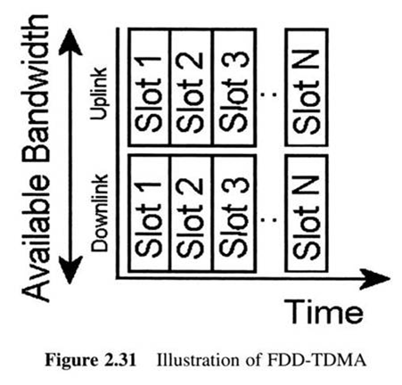
 
In this case, it is logical to expect that portals already flourishing on the wired Internet will have a big advantage over those of mobile carriers
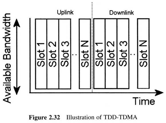
 
In that case, mobile carriers will have the advantage of gaining from the knowledge and customer base of the successful fixed-Internet portal
 
The application service provider role. In the 3G generations and beyond of wireless networks, many new services will appear.
 
Thus, mobile carriers are potential providers
 
The content provider role. Mimicking the world of fixed Internet, mobile carriers will also have to prepare content for their portals

BackToTop
14.3.4.2 Few Carriers
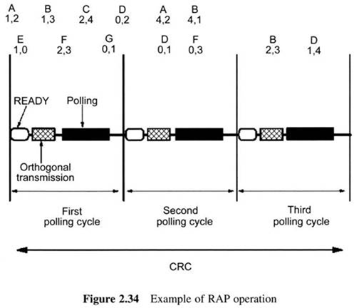
 
 
The cost of the equipment for the rollout of the new services is estimated to be 2-4 times higher than the cost of 2G equipment.
 
This means that a reduced number of carriers is likely to characterize each market.
 
This number is estimated to be between two and four carriers for each country's market
 
The prices of products of a company affect those of its competitors.
 
In such an environment companies implicitly come to a common agreement regarding their prices.
 
This kind of agreement is known as self-enforcing

BackToTop
14.3.4.3 Bundled Products
 
 
In most cases, consumers appear to prefer bundled products.
 
Carriers associated with telecom operators, especially for data services, will have a relative advantage

BackToTop
14.3.4.4 Changing Traffic Patterns
 
 
Increased intra-country mobility, especially within the European Union where a common standard (GSM) is used, increases traffic related to roaming between countries.
 
In some small countries, traffic due to roaming will actually constitute more than half of the traffic exchanged

BackToTop
14.3.4.5 Different Situation in each Country
 
 
Due to the different factors that dominate the telecommunications scene and the society of each country, it is difficult to make predictions on successful carriers

BackToTop
14.4 Wireless Data Forecast
 
 
As stated, wireless data will become a significant part of the traffic over future mobile wireless data
 
A somewhat similar situation with that of the early days of Internet characterizes today's wireless data scene: low data rates, abbreviated user interfaces (e.g. those of the Short Message Service (SMS) and Wireless Application Protocol (WAP)), text-like output and low-resolution graphics

BackToTop
14.4.1 Enabling Applications
 
 
A number of capacity-demanding data applications are expected to be used over wireless networks
 
Some of these applications are briefly highlighted below :
 
Video telephony and videoconferencing. These will be typical mobile multimedia applica?tions.
 
They will offer users the ability to participate in virtual meetings and conferences through their wireless terminals
 
Internet browsing. This will be a significant application.
 
It will be greatly enabled by the emergence of XML, which will enable internet content to be more accessible by wireless devices
 
Mobile commerce. These will offer the ability to make on-line purchases and reservations upon demand without having to be in front of an Internet-connected PC
 
Multimedia messaging. These applications will offer support for multimedia-enhanced messages such as voice mails and notifications, video feeds software applications and multimedia data files
 
Geolocation. Geolocation determines the geographical location of a mobile user.
 
There are two types of geolocation techniques, one based on the handset and the other on the network

BackToTop
14.4.2 Technological Alternatives and their Economics
 
 
There are a number of candidate technologies for offering data transfer in wireless networks. In this section we summarize some of these technologies
 
Cdma2000. This is a fully backwards-compatible descendant of IS-95 (cdmaOne) utilizing the same 1.25 MHz carrier structure of cdmaOne
 
High Data Rate (HDR). This is an enhancement of IX for data services
 
Wideband COMA (WCDMA). WCDMA introduces a new 5 MHz-wide channel structure, capable of supporting voice and average data at speeds up to 2 Mbps.
 
General Packet Radio Service (GPRS). GPRS is a packet-switched overlay over 2G networks.

BackToTop
14.5 Charging Issues
 
 
A fundamental issue in the wireless market is the way carriers charge their customers.
 
Although customers are certainly attracted to new and exciting technologies, most of them will make their choice of carrier based on the charges.
 
Thus, it can be seen that charging policies have the potential to greatly impact the success of mobile carriers
 
There must exist a way for users to be charged for calls terminating at the network of a different carrier.
 
In order to illustrate this scenario, Figure 14.1 shows the charges (in monetary units) when a user of carrier A makes a call to a telephone belonging to a different carrier B
 
Since the scheme of the interconnect agreements required each carrier to form a separate agreement with every other carrier, the International Telecommunications Organization (ITU) devised the international accounting rate system.
 
This actually allowed carriers to charge as much as they wanted for calls terminating on their own network

BackToTop
14.5.1 Mobility Charges
 
 
In most cases the price for placing a call through a mobile carrier is a lot higher than that through a fixed telephone carrier
 
However, despite the fact that mobile calls cost more than fixed ones, these prices follow a declining rate for a number of reasons, such as competition between carriers and the target of making mobile telephony a direct competitor of the fixed system
 
Another interesting issue is the charge for the case of a user that places a call that ends at the network of a mobile carrier.
 
Here, there are two approaches:
 
Calling Part Pays (CPP). This approach, shown in Figure 14.2, is mostly used in European countries.
 
It can be seen from the figure that the caller pays for usage of both the fixed and the mobile networks resulting in a free call for the receiving party.
 
Thus, calling a mobile phone from a fixed one is more expensive than a call placed between two fixed telephones.
 
In order to provide fairness to the callers, mobile numbers are preceded by special codes, which let the caller know that the charge for such a call will be higher than that for a call to a fixed telephone

 
Receiving (called) Party Pays (RPP). This approach, shown in Figure 14.3, is mostly used in the United States and Canada.
 
It can be seen from the figure that the called party pays for usage of the mobile network.
 
Thus, calling a mobile phone from a fixed one costs the calling party the same amount of money as a call placed between two fixed telephones.
 
An advantage of the CPP approach is that it brings no burden on the owners of the mobile phone
 
Finally, the CPP approach is much more likely to be used in marketing.
 
This is because most of the time mobile carriers advertise themselves based on the cost of placing a call from a mobile phone, which is continuously declining due to competition

BackToTop
14.5.2 Roaming Charges
 
 
Figure 14.4 shows the case of a call placed from a fixed telephone to a user of a mobile carrier, who has moved to the operating area of a mobile carrier located in a different country.
 
This situation is known as roaming and imposes relatively high charges on the receiving party
 
Thus, the cost of the call for the calling party is just the sum of the cost of using the fixed network and the cost of using the home mobile network

BackToTop
14.5.3 Billing: Contracts versus Prepaid Time
 
 
Once the charges for utilizing network resources are summed up, the mobile carriers have to send bills to the customers in order to get their money.
 
There are two main approaches here: contracts and prepaid billing.
 
A contract is essentially leasing of a connection to the network of the carrier
 
Of course the user is also charged for both the calls made and generally for all the services used
 
Contracts have the disadvantage of limiting the user to a specific carrier for a certain amount of time
 
Thus, another approach appeared; that of 'prepaid' time
 
According to this, users pay in advance for both their handsets and the calls they make
 
Once the user of the phone has exhausted all the credits, he/she can recharge the phone by entering special code numbers that can be found on special cards sold by stores, automatic teller machines, etc
 
The advantages of the prepaid approach are that:
 
Since no monthly charged is employed, customers have greater control of their costs,
 
From the operators point of view prepaying is beneficial since they get their money in advance and are not burdened with the overhead and cost of producing bills for prepaid customers,
 
Prepaid is beneficial for users who would otherwise not have a credit rating sufficient to qualify for a contract mobile subscription

BackToTop
14.5.4 Charging
 
 
There are three main motivations for charging in mobile wireless networks.
 
These are briefly highlighted below:
 
Recovery of the investment in infrastructure equipment.
 
Generation of profit for the mobile operators and service providers.
 
Controlling network congestion by providing service levels of different prices.
 
For the case of noncommercial organizations, such as schools and universities, congestion control through a charging scheme is used for social reasons
 
Charging methods largely depend on the structure of the network.
 
The majority of wireless networks until the 3G era were primarily designed for voice traffic and are thus of a circuit-switched network.
 
Nevertheless, the movement towards the next generation of wireless networks is towards a packet-switched network
 
Circuit switching is efficient for data traffic, since in such cases the circuit will be idle most of the time.
 
Packet switching solves this problem by routing packets
 
A benefit of using packet switching for data services is that bandwidth is used more efficiently
 
Furthermore, in a packet-switched network, priorities can be used.
 
Packet switching has emerged as an efficient way of handling asynchronous data in cellular systems
 
The rising significance of data traffic over wireless systems makes the importance of using packet switching in such systems even greater

BackToTop
14.5.4.1 Charging Methods
 
 
Below we describe some methods for charging in mobile networks
 
Most of these methods have already been proposed for the Internet but are equally applicable in the case of mobile networks
 
Metered charging. This model is already used by many ISPs, mobile and fixed telephony carriers.
 
The model charges the subscriber with a monthly fee irrespective of the time he spends using the network services.
 
This method is used in 2G networks for charging voice traffic
 
Packet charging. This method is used for charging in packet-switching networks.
 
It is more suitable for data than metered charging.
 
This is because the user is not charged based on time but rather on the number of packets that he/she exchanges with the network
 
The disadvantage of packet charging is the fact that its implementation might be difficult and thus costly
 
Expected capacity charging. This method involves
 
(a) an agreement between the user and the carrier regarding the amount of network capacity that will be received by the user in the case of network congestion
 
(b) a charge for that level of service
 
The advantage of this method is that it enables mobile carriers to achieve a more stable long-term capacity planning for their network
 
Paris-metro charging. In this method, the network provides different traffic classes, with each class characterized by different capabilities and hence a different charge
 
it is obvious that Paris-metro charging is useful for providing network traffic prioritization in wireless data networks.
 
Another advantage of the method is that it provides customers with the ability to control the cost of their network connections.
 
However, the disadvantages of the method are
 
(a) an increase in the mathematical complexity of the network's behavior and thus cost of implementation and
 
(b) the fact that users need to be familiar with the process of assigning traffic classes to their connections introduces some overhead for them
 
Market-based reservation charging. This method entails an auctioning procedure for acquiring network resources.
 
Users place monetary bids and based on these bids the network assigns appropriate connections to users.
 
An advantage of this method is the fact that users are in control of the quality of service they receive from the network
 
However, because of the disadvantages of this method it is generally agreed that this method is no suitable for the wireless Internet
 
Figure 14.5 summarizes some characteristics of the above charging methods
 
By utilizing such a combination of charging schemes, the required charging policy for a diverse range of customer types, ranging from teenagers and students to business users, can be achieved

BackToTop
14.5.4.2 Content-based Charging
 
 
A different approach to the problem of how to charge a customer for utilizing the network is content-based charging.
 
The novelty of this approach is that users are not charged based on usage, but rather on the type of content they access.
 
Some examples of the significance of content-based charging follow:
 
Content-based charging has been applied in Japan by NTT DoCoMo
 
Another example is the case of the Short Message Service (SMS)
 
Another example is that of on-line games through the wireless Internet

BackToTop Wed Mar 16 00:34:06 CST 2011